PixelMapping
Introduction
Pixelmapping enables you to control the color of lighting equipment using movies. This is typically used to synchronize the color of the videomapping with the color of the lighting.
In this example a small gradient video controls a LED ribbon using the ArtNet protocol.
Onlyview can also record ArtNet from a lighting console, and play it back later; See the documentation of the ArtNet device.
Glossary
DMX: Hardware protocol, using dedicated cables and connectors, used to control lighting equipment. A DMX cable can carry 512 values, so 170 RGB pixels max.
ArtNet: Ethernet version of DMX. Can carry many DMX “cables”, called “Universes”. Some hardware is directly ArtNet compatible; for DMX-only hardware, converters are needed.
Channel: Identifies a specific value of a DMX universe amongst the 512.
Output: The network card of a Display. Identified by its IP address. A single Display can have multiple network cards.
Patch: A zone of a screen (or TextureArea) that is pixelmapped on a specific ArtNet address. A single Output typically has multiple Patches.
Fixture: Describes how a particular hardware model expects its data. A LED ribbon can be 100px long but only 1 pixel wide; a panel can be 12x12. Some equipment expects RGB data, some RGBW. A fixture describes this. A fixture can be re-used: if you have 10 Maverick MK3, you only need to describe them using 1 fixture.
Setup
Just like audio, pixelmapping needs to be enabled on specific Displays.
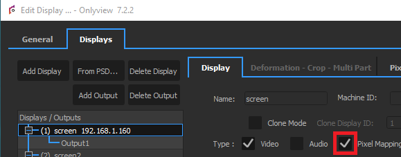
This will give you access to the PixelMapping tab.
Create an Output and fill its IP. This is the IP address of the network card that is installed inside the Display, and which will be used to send the pixelmapping data.
Inside this Output, create a Patch. There are three important parts in a Patch.
Fixtures
The first part of the patch is the fixture. As explained in the glossary, it represents how the DMX hardware expects its data. Click on “Setup”, then add a new fixture.
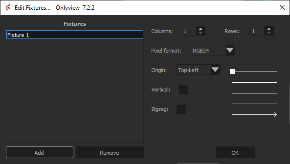
The number of columns and rows is usually straightforward.
The pixel format depends on the model and can be found in the hardware’s documentation, but it is normally RGB.
The Origin, Vertical and ZigZag fields depend on how the panel is internally cabled. The schema on the right gives you an indication of how the physical layout.
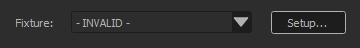
Validate, then select which Fixture you want for a particular Patch.
Input
Input: A Patch can take its data from any screen of the Display, but also from TextureAreas.
Position/Resolution/Rotation: Selects a particular part of the input screen/TextureArea.
Color adjust: A simple multiplicative factor for the output color. For more control over the colorimetry, directly adjust the colorimetry of the cue.
Output
This part describes where to send the pixels’ colors.
Net/SubNet/Universe: On which DMX universe the data will be sent. A single Output can use up to 1000 different Universes.
Channel: A single Universe contains 512 values, so many projectors can fit inside. This field represents the first channel to fill for this particular patch. For instance, if a fixture uses 6 bytes, the first patch can use Channel 1, and the second patch can use Channel 6, and so on, up to 512.