The Content window
The Media Server List
Overview
An Onlyview Media Server is a computer that decodes the videos and renders them on the videoprojectors.
The MEDIA SERVERS tab contains the list of Media Servers that are part of the show. In particular, it shows the status of all the Media Servers, and allows to edit them.
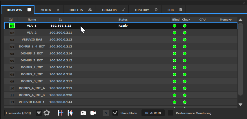
The Media Servers are shown using the following color code:
gray : not connected yet
orange : loading
gray with a green icon: ready, the Media Server is connected and listens to Producer commands
red : error
The Media Servers list
The important columns of this table are :
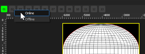
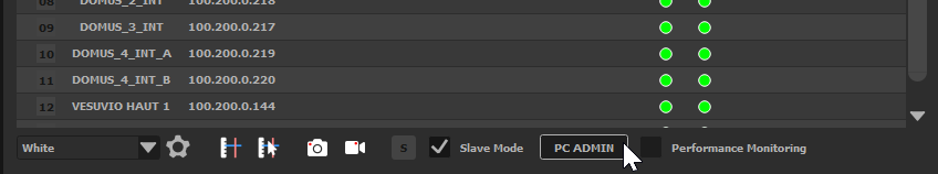
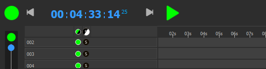
- ID: Each Media Server has an identifier in the show. This identifier is visible at other locations, so that you can monitor the Media Server’s status, for instance at the top of the 2D preview:
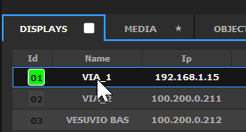
Name: Each Media Server has a user-provided name; this is usually in relation with the zone of the show that is handled by this Media Server, for instance «Towers» or «Floor»
Blind: A blind Media Server (black icon) will not receive any network command.
Clear: A Media Server that is cleared (black icon) will behave normally, and receive network commands, but will remain fully black.
CPU & Memory: Performance monitoring, see the full reference section.
To edit an existing Media Server, double-click on it. The ``Edit Media Server`` dialog opens.
To add a new Media Server to the show, you can either double-clic on an empty zone, or use the ``Add Screen`` button of the ``Edit Screen`` dialog. Media Servers that are connected on the network will automatically appear in the list; click on “+” to add them to your show.
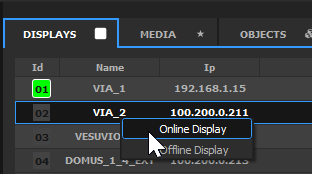
Although Media Servers are usually put Online using Ctrl-O, you can also Online/Offline them individually using the right-click menu.
Mires
Onlyview provides several built-in mires. They are either used to help with the calibration process, check the video signal, or monitor the performance during installation.
The various mires are:
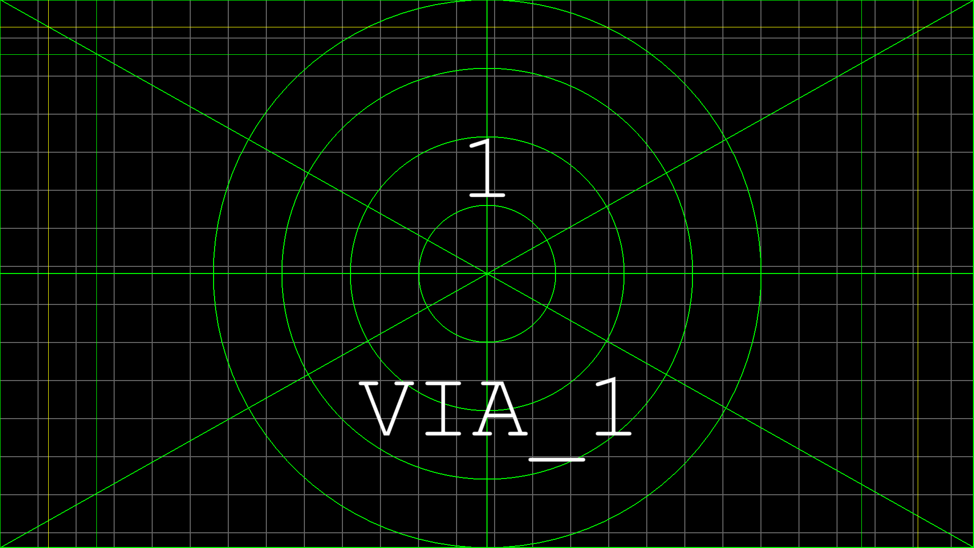
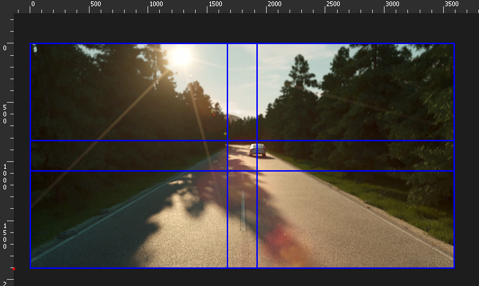
Small Pattern. Used for aligning the projectors, and to finetune the softedges. It consists in:
A gray grid of 75 pixels, to check the alignment with the other projector
A color outline, to see the limits of the projector
The ID and the name of the Media Server
When manual softedge is used (here: on all sides except the bottom), extra lines are drawn, that should overlap with the other projector to get a good first approximation, before finetuning.
The width and the color or the lines of this mire are configurable:
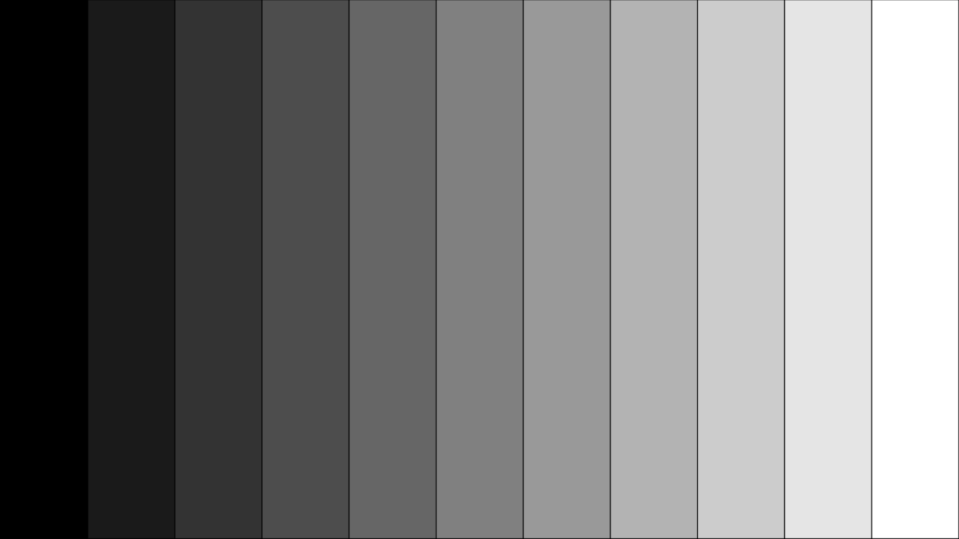
- Horizontal and Vertical black levels
- Tiles

- Onlyview Logo

- Color bars

- On Screen Display: Shows the status of all the different timelines
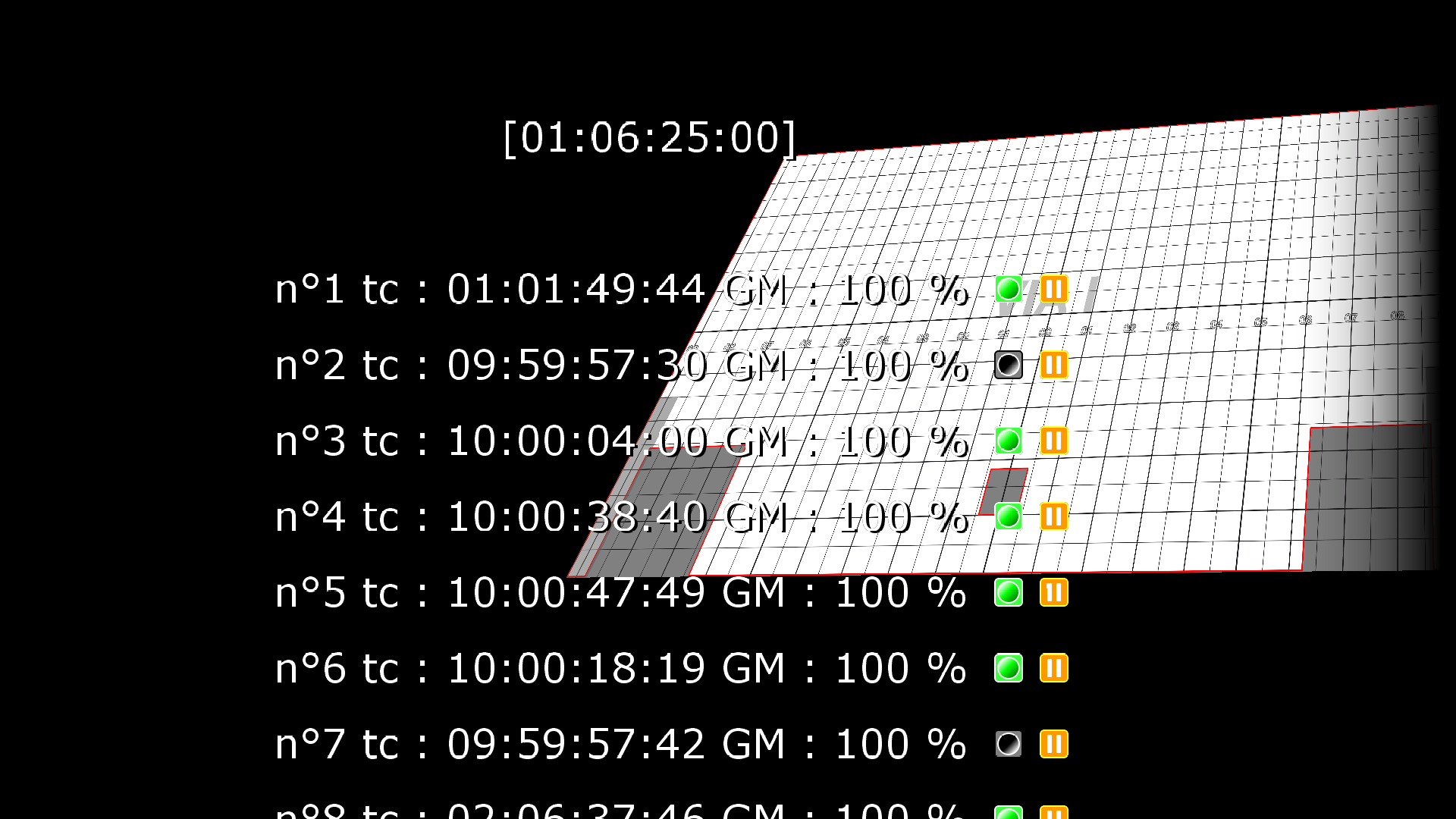
- Framerate (CPU): Time spent on each frame.
The middle horizontal line corresponds to the duration of 1 video frame. For instance, at 50Hz, it corresponds to 20ms. The vertical lines are the time spent by the CPU on each frame, so the green graph should always remain below the middle line. Otherwise, the video will stutter.
The top horizontal line corresponds to the duration of 2 video frames (so 40ms at 50Hz). This is useful when working with big 25Hz media on a 50Hz projector, because in this case, displaying at only 25Hz may be acceptable.
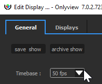
The framerate used as a base is the one of the show: File -> Show options -> Timebase.
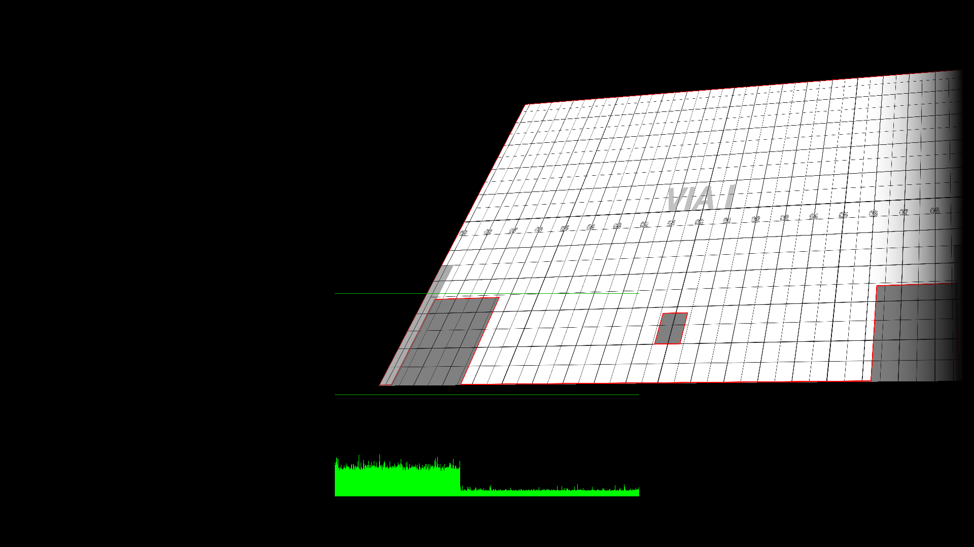
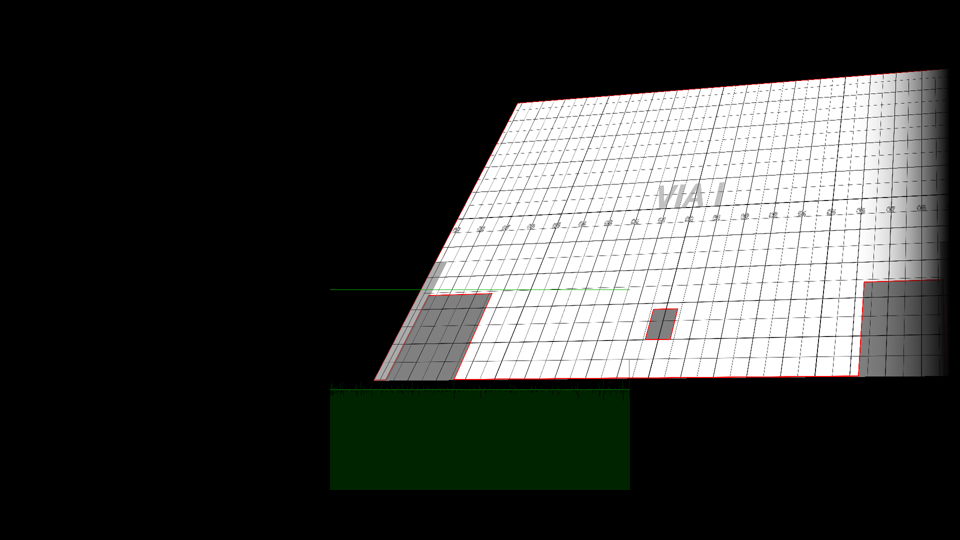
- Framerate (GPU): This is similar to the CPU graph, except it’s the time use by the graphic cards, including «presentation» ( waiting for the vertical sync of the projector). As such, it is most of the time on the middle line. If you start dropping frame due to performance issue, the graph will start jumping to the top line.
- White: just a full white
PC Admin
The PC Admin is used to control parts of the Media Server that are not related to the show: Starting and stopping it, rebooting the computer, remote upgrades…
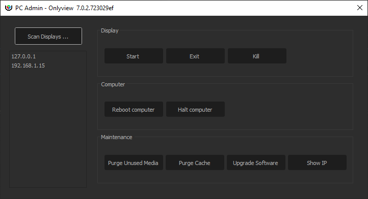
“Scan” scans the network for connected computers. Onlyview’s Watchdog must be running on the Media Server for the scan to be successful.
Start/Exit/Kill: Starts or stops display.exe. Kill is only used when display.exe is stuck.
Reboot/Halt: Reboots or stops the computer
Purge unused media: Media Server stores the medias in a cache (usually D:/cachev3). When removing old medias from the show (maybe because the creative team provided you with a newer version), the cache should be cleared to reclaim SSD space.
Purge cache: fully clears the cache. This includes the medias that are currently used, and also the cache from other shows.
Upgrade software: uploads a new version of display.exe to the remote computers
Show IP: The IP adresses of the Media Servers will be shown in fullscreen
Full reference
Configuring the Media Servers
Overview
The Edit Media Server dialog is used to connect new Media Servers to the shows and edit them.
Adding a Media Server
To add a Media Server, click on ``Add Screen``, and enter the Media Server's MachineID (as printed on the case of the server).
You can also give it a representative name. The IP and MAC addresses will be auto-completed on the next Ctrl-O.
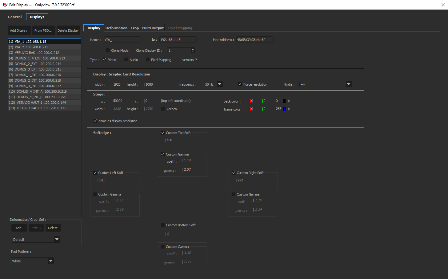
Configuring a simple Media Server
By default, a Media Server is configured to output a single FullHD stream.
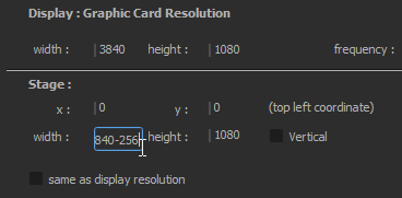
This can be edited in the Graphic Card Resolution section.
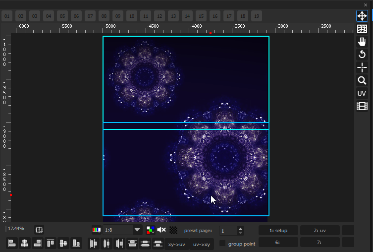
The Stage section delimits which part of the stage this particular Media Server will show.
Usually, different Media Servers will show different parts of the stage. In this simple example, there is one Media Server for the top of the media, and one Media Server for the bottom. They overlap on the middle to allow for a smooth transition between the projectors (softedge).
Configuring a Media Server with specific output types
In addition to basic HDMI/DisplayPort video output, you can create other types of outputs: - SDI - NDI - Spout - SMPTE 2110
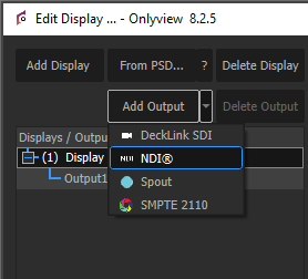
A Media Server requires at least one basic output in order to work. Synchronization between different type of outputs is not guarenteed.
Media Server tab full reference
Name: A representative name for the Media Server.
MachineID : Corresponds to your license; printed on each case.
IP: The IP address of the Media Server. It is automatically filled during the Ctrl-O.
Mac Address: Used for Wake-On-LAN. It is automatically filled during the Ctrl-O.
Clone Mode & Clone ID: When using Clone Mode, the current Media Server will ignore all its settings, and use the ones from the Clone Media Server ID instead. A single Media Server can be cloned multiple times. This is usually done to overlay multiple projectors to increase luminance. Note, however, that this forces to do keystone adjustments directly on the projector, since the deformation will be shared between all clones; to avoid this, you can use a real Media Server instead, and import the deformation from the original Media Server.
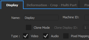
Type: A Media Server can play Video, Audio, and Pixel Mapping (via Art-Net). By default, only Video is enabled. Ticking «Pixel Mapping» enables the related tab.
Version: This field shows the version of display.exe that is running on the remote computer. It must match the version of Producer, otherwise a warning is shown. A Ctrl-O is needed to update this field.
Graphic card resolution
Width, height, frequency: The resolution & frequency of the projector that is attached to the Media Server. If you have multiple projectors connected to a single Media Server, you need to create several Outputs for this Media Server.
Force resolution: When checked (the default), Media Server will switch to the user-provided resolution. If not checked, it will remain in whatever resolution it previously was.
Stage
Stage x, y, width, height: This delimits the zone of the stage this particular Media Server will show.
Same as display resolution: By default, a 1920*1080 Media Server will capture a 1920*1080 zone of the stage – and the position of this zone is set using Stage X and Stage Y. But this zone can also be bigger or smaller. If the ratio is not kept, the output image will be stretched, which may be desirable.
Back color: The background color of the Media Server, i.e. the color when no cue is shown on top. Black by default.
Softedge
When multiple Media Servers overlap on the Stage, a softedge will automatically be computed by Onlyview so that the two projectors blend perfectly. This feature is enabled in Display Setup -> General -> Enable Softedge.
For a variety of reasons, this feature may not be sufficient:
You need to finetune the automatic 2D softedge
You organized the Media Servers so that they do not overlap on the Stage to ease compositing
Softedge may then need to be customized.
Length: In pixels, how high/wide the softedge will be. As a rule of thumb, you should arrange your projectors to allow for approximately 15% softedge.
Gamma: Projectors usually output in sRGB. This means that the hardware internally applies a gamma of roughly 2.2 to the pixel colors given by Onlyview. This must be taken into account when doing the transition from one projector to another, so that visually, the luminance remains constant, and the “seam” as invisible as possible.
With and without gamma correction:

Offset: Helps finetuning the gamma curve. 1 means no offset. 1.1 means that the end 10% of the softedge will be fully black. In other words, the softedge will only use 90% of the available pixels.
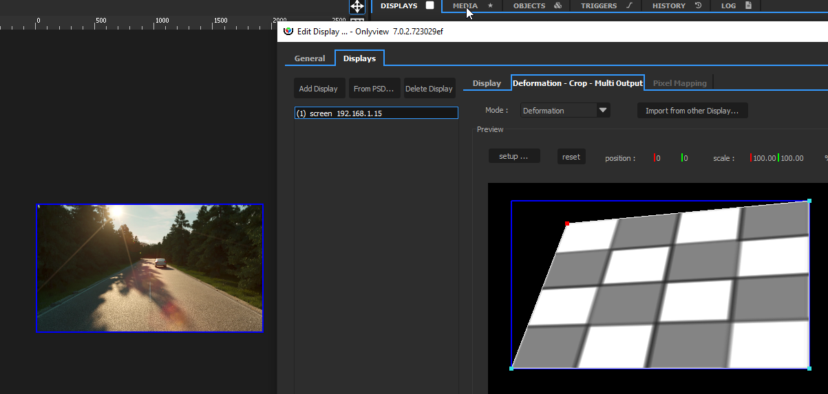
Deformation & Multi-Output tab
Overview
In the Deformation tab, you can do simple deformations to your output feed.
By default, new screens are in Simple mode - that is, no deformation can be applied. This mode is slightly better for performance.
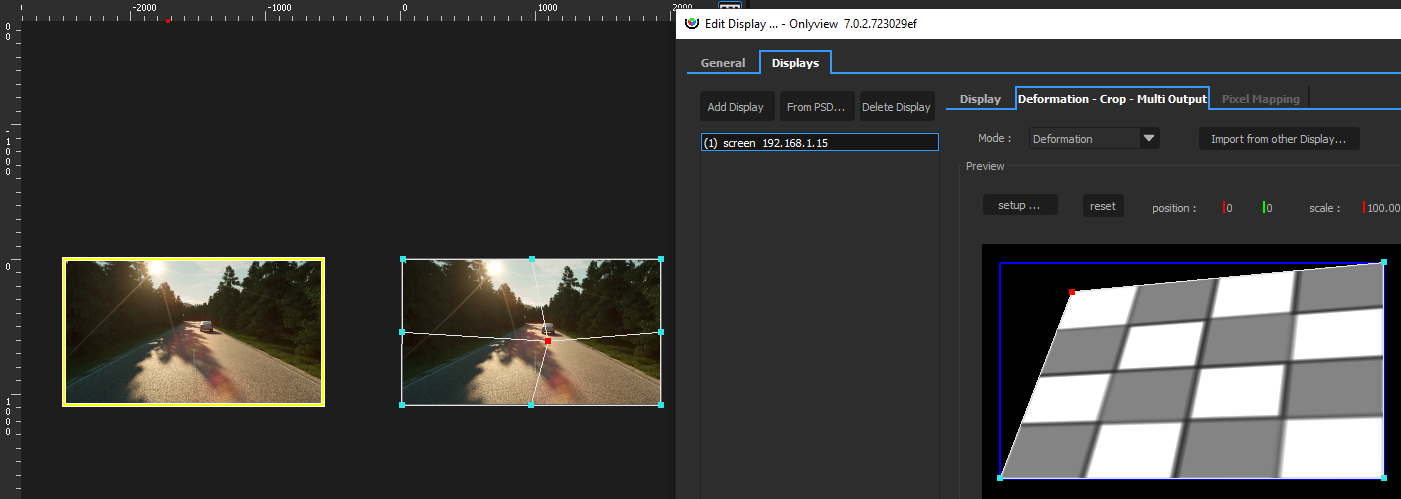
In Deformation mode, you can deform the screen using either a Keystone deformer, or a Curve deformer.
- Keystone deforms the whole screen using only the four corners, while maintaining a correct perspective deformation.
- Curve offers more control.
The Multi-Output mode renders multiple views in a single feed. See the related section below.
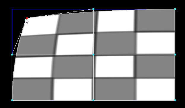
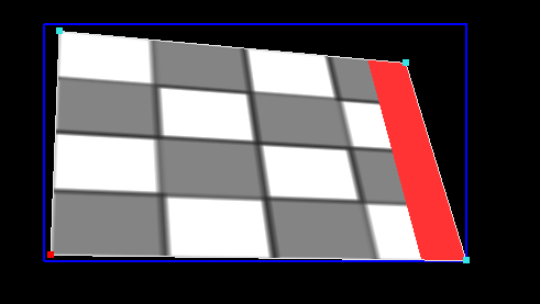
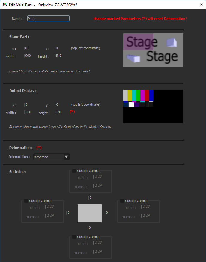
Each part can then be deformed individually.
Crop
The output can be cropped on all sides. Cropping is impacted by the deformations:
Simple
Simple mode does not do any deformation. This is the default mode, because it is slightly better for memory and performance.
Deformation
This mode deforms the whole screen. The memory and performance hits are similar to using an extra TextureArea.
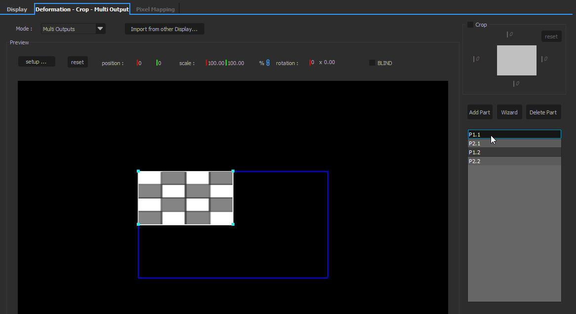
Multi-outputs
This mode makes it possible to deform several parts of the screen individually. It is most commonly used in conjunction with NVIDIA Surround or Mosaic. Multiple projectors are arranged on a single extended desktop. OnlyView just sees a single big screen (for instance, 4*4K). The multi-output feature can then be used to assign a different zone to each 4K part of the extended desktop. This feature makes it possible to have good synchronization with non-professional GPUs; However, it is recommended to use Quadro cards instead.
Example:
We have 1 Media Server with 2 FullHD projectors, arranged horizontally. We want a 256px overlap for the softedge. So, we have a 2*1920=3840px wide screen, but our media must be 256px narrower, so 3840-256=3584px.
In the Multi-output tab, click “Wizard”, and input 2 horizontal parts, with a 256px overlap.
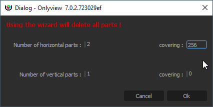
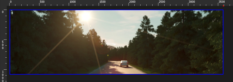
This will generate 2 parts, with the correct overlap, and the correct softedges. On the 2D stage, the Media Server will appear to take 3584px.
The middle part will be rendered twice, once for the left projector, once for the right projector.

Other ways to deform the output
Note that there are other means to deform the output:
- In this first example, the media is placed directly on the Media Server, and the Media Server is then deformed. This is the simplest setup.
- You can output your media in a TextureArea zone, then show this TextureArea in the Media Server's zone, and deform it
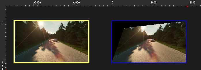
- You can combine both (do the main keystone in the Deformation tab, then fine-tune by going through a TextureArea)
- When using a 3D scene, the deformation will be handled by the 3D mesh. But fine-tuning is usually needed; it can also be done either in the Deformation tab, or by going through a TextureArea.
EDID Settings
EDID (Extended Display Identification Data) management allows you to configure your GPU outputs in advance, without having the actual monitors connected. This is particularly useful for pre-show setup, testing, and maintenance scenarios where you need to prepare Media Server configurations before the actual hardware is available.
Overview
The EDID Settings dialog is accessed from the Media Server configuration window and provides tools to manage display identification data on professional GPUs. This feature requires professional graphics cards (Quadro, Tesla) and is only available on Windows systems.
Understanding EDID
EDID contains information about a display device including: - Manufacturer and model information - Supported resolutions and refresh rates - Color capabilities and gamma characteristics - Physical dimensions and orientation
When a monitor is connected, the GPU reads this information to determine optimal display settings. By “locking” an EDID, you can preserve these settings even when the physical monitor is disconnected.
EDID Operations
- Lock EDID: Captures the EDID from a currently connected monitor and stores it on the graphics card. This allows the monitor to be disconnected while maintaining the same display configuration. The GPU will continue to behave as if the monitor is still connected. -Export EDID: Saves the EDID data from a connected monitor to a file (.txt or .bin format). This is useful for backing up monitor configurations or sharing them between different systems. -Load EDID: Applies a previously saved EDID file to selected GPU connectors. This allows you to configure outputs with known-good monitor settings even when those specific monitors aren’t connected. -Unload EDID: Removes any custom EDID override and reverts to using the EDID from the physically connected monitor (or no output if no monitor is connected).
DisplayPort Dual-Mode
DisplayPort connectors can operate in two modes: - DisplayPort mode: Used with native DisplayPort monitors or active adapters - Dual-Mode (DP++): Used with passive HDMI adapters, where the GPU outputs HDMI signals over the DisplayPort connector
When configuring disconnected outputs, you need to specify which mode to use via checkboxes in the EDID Settings dialog. If in doubt, connect the actual hardware first to see which mode is automatically detected.
Usage Requirements
- NVIDIA Quadro GPUs are required (consumer GPUs don’t support EDID override)
- Windows only
- Administrative privileges (automatically handled via the elevated helper service)
- Connected monitor for Lock and Export operations
Typical Workflow
- Connect your target monitor to the Media Server
- Open the Edit Media Server dialog and click “EDID Settings”
- Select the connector in the tree view
- Click “Lock” to capture and override the EDID
- The monitor can now be disconnected while maintaining the same output configuration
- Use “Export” to save the EDID for future use on other systems
- Use “Unload” when you want to revert to physical monitor detection
Status Indicators
In the EDID Settings dialog, connectors show their current status: - Connected - Monitor: Using EDID from the physical monitor - Connected - File: Using a locked or loaded EDID override - Disconnected: No monitor connected - Error: Connected but unable to apply EDID
General tab
This tab handles settings that are common to all Media Servers.
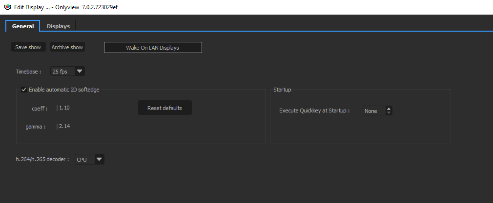
The most important one is the timebase, which dictates how timecodes will be interpreted across the whole show: setting 25fps here will, in particular, impact the timelines:
Enable automatic 2D softedge: When multiple Media Servers overlap on the Stage, a softedge will automatically be computed by Onlyview so that the projectors blend perfectly. For instance, in the following show, there are 4 FullHD Media Servers, with a 256px overlap:
Using this option, the top-left Media Server automatically shows the media with the softedge applied.

The gamma and offset parameters are global parameters that apply to all Media Servers, and that can be finetuned per-Media Server using the Custom Softedge parameters, available in the Media Server tab.
The Media list
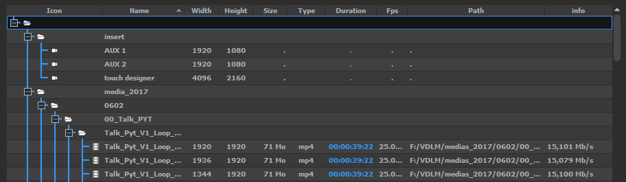
The MEDIA tab contains the media list, which shows all the media that have been added to the show, and are ready to be used on a Timeline:
Supported medias
Onlyview supports the following media types:
Video: Image sequences, MPEG-2, h.264, h.265, HAP, HAP-Q, HAP-a, HAP-Qa, NotchLC, ProRes (all variants)
Images: TGA, PNG, JPEG, BMP, PSD (with independent layers), TIFF
Sound: WAV, AIFF, FLAC, MP3, OGG
Streaming: SDI (using Decklink cards), NDI
Generative content: Notch, Spout (for Unreal Engine/ Unity/ other)
Adding a new media
The most common way to add a media to the media list is to use the Add Media button:

You can also import a whole folder using the Add Folder button; or directly drag&drop a media in the list.
One exception is Image Sequences: you need to use the Add Image Sequence button instead.
TextureAreas
TextureAreas capture a part of the stage; and this capture can be re-used at a different place.
They are similar to Compositions in other software.
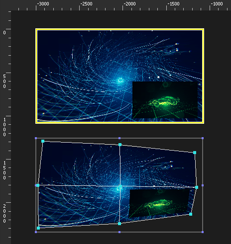
In this example, a TextureArea captures 2 medias that are overlayed. The capture zone is delimited by the yellow rectangle.
The TextureArea can now be used as a regular Cue (below). Its content will behave as a normal media: deforming the cue will now deform the blue video and the green video at the same time.
It is common practice to render all the medias into a TextureArea, and not directly into the Media Servers. This has several advantages:
This separates the “content” part of the Show from the “calibration” part: The media just go in the TextureArea, without taking anything else into account; and the deformations/calibration/colorimetry is done once, elsewhere.
In a 2D workflow, it makes it easy to create deformations by cutting small parts of the TextureArea, and mapping them independently:
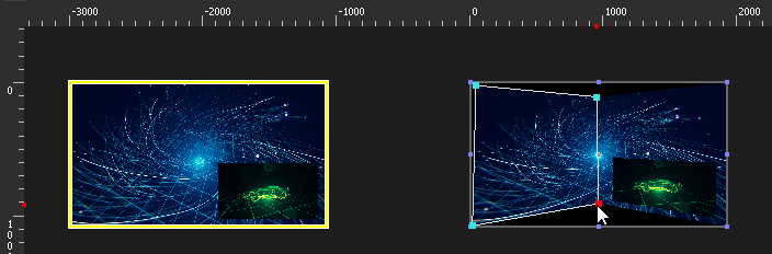
- In a 3D workflow, TextureAreas are required to show content on a 3D mesh.
AntiAliasing: How many samples will be stored for each pixel. Note that antialiasing is important when receiving a deformed cue:
When rendering a FullHD media in a FullHD TextureArea without deformation, antialiasing is useless – there is already a 1:1 match between pixels.
Rendering a x8 perfectly antialiased TextureArea into a non-antialiased screen will still produce hard edges.
So antialiasing should usually be set on the “receiving” TextureArea.
Pixel format: The pixel format impacts the quality and the memory/performance of rendering in the TextureArea, and displaying the TextureArea cues.
8 bits for color, 8 bits for alpha: This is the default, which provides the usual 256 colors per channel, and 256 levels of transparency.
10 bits for color, 2 bits for alpha: Used when working with opaque 10-bit media
12 bits for color, 12 bits for alpha: Used either when working in 12 bits, or when the previous mode does not handle alpha well enough.
16 bits for color, 16 bits for alpha: Usually overkill.
Note that when using a 10-bit TextureArea or above, it’s important that the next surface in the pipeline is 10-bit too, otherwise this extra precision will be lost in an 8-bit buffer. In particular, see DisplaySetup pixel format settings.
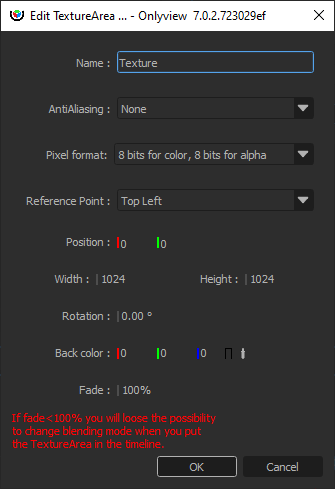
Reference point: Which corner the position sets. The rotation is expressed with respect to this point.
Position: Position of the TextureArea, in Stage coordinates.
Rotation: Rotation of the TextureArea, in degrees.
Back color: Background color of the TextureArea. Opaque black by default.
Fade: Opacity of the background. Fully opaque by default.
Decklink SDI input
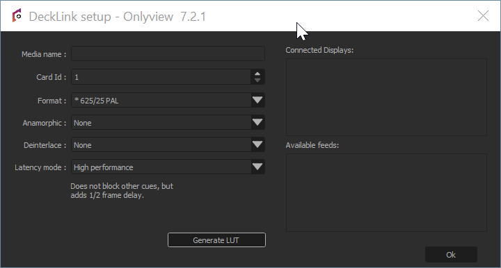
Onlyview can use Decklink acquisition cards to input SDI signal. The basic usage is to click on the Add Decklink Media button:

Media name: A name that is meaningful to you.
Card Id: There can be multiple Decklink card on a computer, each with multiple ports, which can be configured individually using the Decklink tool. So unfortunately, there is no good way for us to know which ID corresponds to which port, so you often need to test them all...
Source: Depending on the model, Decklink cards can input SDI only, or HDMI, Optical SDI…
Format: This is needed to initialize the cue’s dimensions, and to check that the input signal corresponds to the required format.
Anamorphic: The cue can be rescaled vertically to take anamorphic scaling into account.
Latency mode:
High performance: This is the default. When rendering the frame, Media Server just draws whatever image arrived last.
Low latency: Media Server waits a few milliseconds until a new image arrives. The advantage is less latency; the drawback is that frames take longer to render. And if you are not genlocked, the frame duration will vary at each reboot. You can monitor the frame duration using the CPU mire.
The Card ID is also impacted by DisplaySetup:
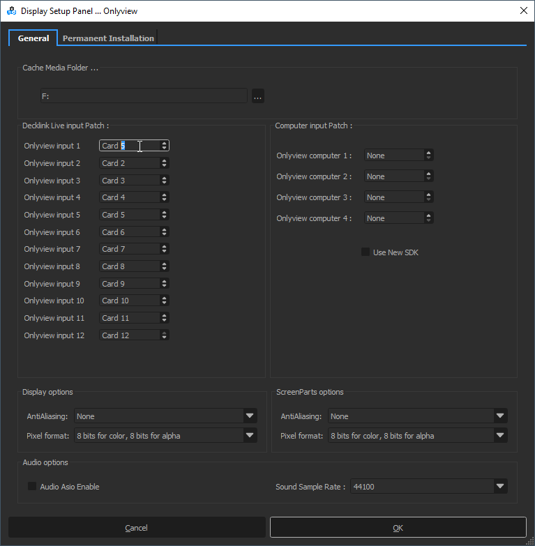
Since all Media Servers are not necessarily wired in the exact same way, “Decklink Live input Patch” can add exception for specific machines. For instance, in the screenshot above, trying to use Card #1 will in fact use Card #5 on this Media Server.
NDI
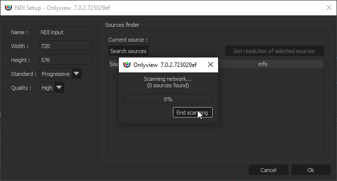
An NDI media can receive an NDI stream, that is, a video stream that is h.264-encoded, and transported over IP.
Width, Height: Size of the cue; does not necessarily match the resolution of the NDI stream.
Standard: This setting should currently be set to Progressive.
Quality: High (the default) or Low (allows for bandwidth gains)
NDI sources are exposed on the network, and are discoverable. To scan the network for existing senders, click “Search sources”. This will allow you to auto-fill the parameters above.
Spout
A Spout receiver can share a GPU buffer with a separate Spout-enabled application, for instance Unreal Engine or Unity3D.
This makes it possible to add real-time generative content into Onlyview.
Note that the 3rd-party application must run on all Media Servers at the same time. As such, they need to provide deterministic behavior. In particular, particles are often problematic.
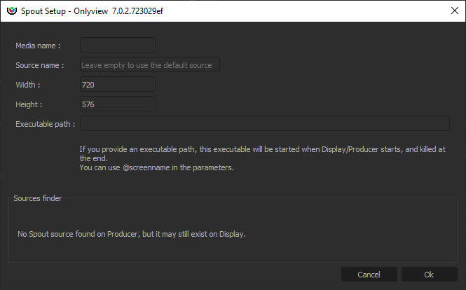
Media name: A name that is meaningful to you
Source name: Each Spout sender identifies itself by its name. There are several options:
If you know the name, just enter it.
You can run the sender on Producer; the source will then appear in the Sources finder.
If there is only 1 source, you can leave the field empty, and Spout will auto-select the first source.
Width/Height: The size of the cue. Does not need to match the stream resolution.
Executable path: The content is provided by a separate executable. You can start and stop it manually, but this is cumbersome, because this needs to be done on all Media Servers, which are usually not easily accessible.
Instead, Onlyview can start and stop if for you: If you enter D:/path/to/my/content.exe, each Media Server will start the application at Ctrl-O. This is still problematic because you have to copy content.exe on all Media Servers; so an easier way is to use a shared folder, for instance \\creative-pc\share\content.exe
You can also pass command-line arguments to the executable, like --no-fullscreen or --currentscreen=@screenname , so that you can add extra logic in your application depending on which Media Server it is running on.
Text
A basic text media that can be edited.
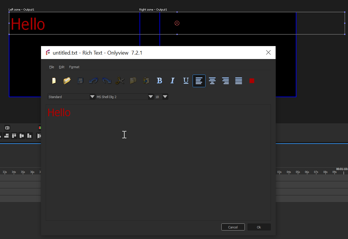
Limitations – You need to set Windows’ desktop scaling to 100% on both Media Server and Producer, so that the rendering is consistent between all machines.
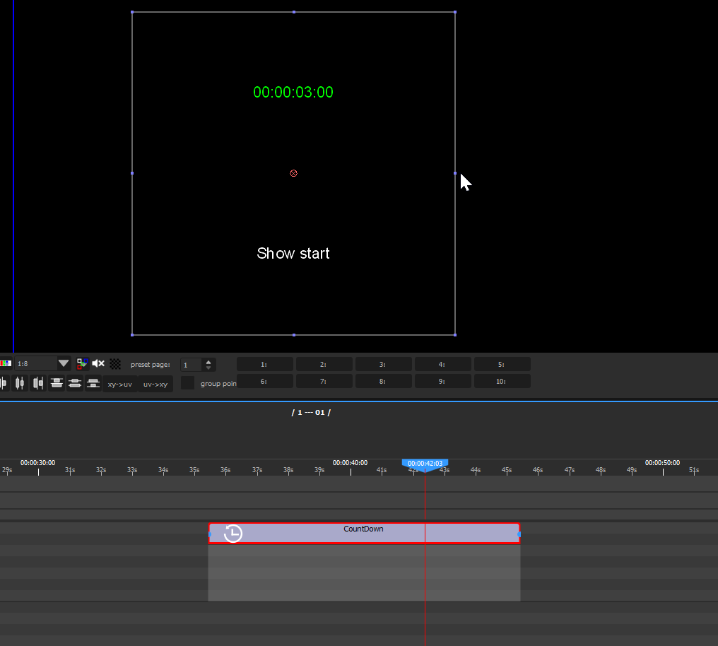
Countdown
A countdown media displays a clock that can be used to foresee how many seconds remain before another cue starts playing, for instance:
Audio
Onlyview accepts the following audio formats: aif, mp3, wav, ogg, flac.
For a Media Server to play audio, it must be enabled in the Edit Media Servers screen:
Onlyview can either output on standard audio cards, or in ASIO for compatible cards. ASIO is required for multi-channel audio.
The output card and the output frequency are selected in DisplaySetup (also accessible in Edit Media Server). If the input file does not have the correct frequency, it will be automatically resampled so that it plays correctly.
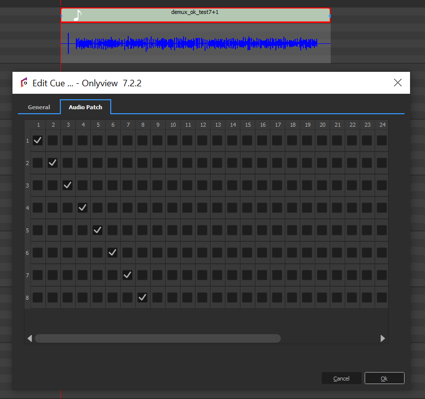
Editing an audio cue also gives access to the patches: each input channel can be remapped to any output channel. Input channels can also be played on multiple outputs, or muted entirely.
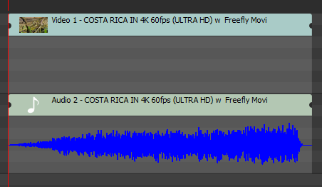
When importing a movie container (MP4, MKV, …), all audio streams will also be listed in the media list:

Dragging the container in the timeline will create multiple cues, one for each stream. This allows for fine synchronization between audio and video.
Selective Upload
Selective Upload gives the user more control over which Media Servers each media is uploaded to.
Use Cases
Normally, all media are uploaded to all Media Servers. However, in some cases, it is desireable to prevent some Media Servers from getting the file:
- Large videos can be divided into multiple parts for different Media Servers for playback performance (e.g., left half and right half of a wide screen)
- Preventing large media files from being stored on Media Servers where they won’t be used
- Manually optimizing the upload time when some Media Servers don’t need a file
How to Use
This feature is available for both individual media files and TextureAreas. To configure selective upload:
- Right-click on a media or TextureArea in the media list
- Select “Selective Upload” from the context menu
- In the dialog that opens, choose which Media Servers should receive the media
- Click “OK” to apply the settings
The dialog shows each Media Server with options to either upload or not upload the selected media. Changes take effect on the next Ctrl-O.
Full reference
Full reference
Edit Screen keyboard shortcuts
Screen preview
- Pan view: Middle click & drag
- Zoom: Wheel
- Same deformation keyboard shortcuts as in the 2D preview
Pixel mapping preview
- Pan: Middle click & drag
- Move, scale, rotate patch: Left click & drag on appropriate zones