3D preview
Onlyview offers a full-3D workflow to adapt to the most complex stages.
Fundamentally, the advantage of working in 3D is mostly that you don’t have to handle precise deformations by hand on very complex models. You should receive a mesh from the creative team or from a 3D scan, and Onlyview will display the scene with the correct deformation.
But Onlyview’s 3D tools also bring you many extra bonuses: automatic softedges even on complex and moving surfaces; manual and automatic projector calibration systems; and multiple analysis and projection study tools.
Creating a scene
This section will briefly explain the basic steps of creating your first 3D-based show. Each feature will be explained in more details in the next sections.
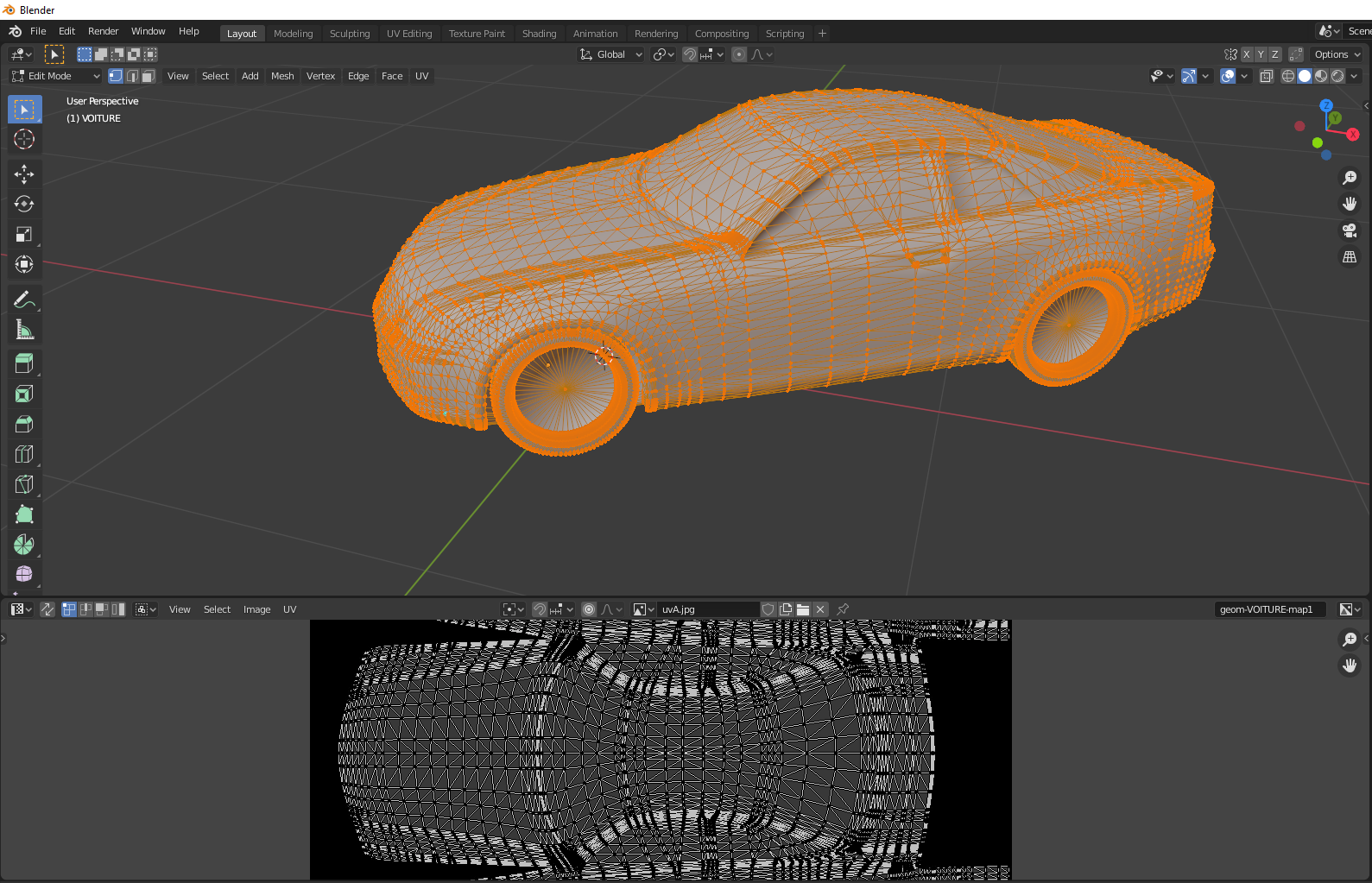
FBX preparation
Prepare your 3D scene in a 3D modeling package. Examples include Sketchup, Cinema4D, 3DsMax, etc. Then, export your scene in FBX. Ideally, use meter units during the export, as this will simplify the process later.
You can also create simple shapes directly in Onlyview.
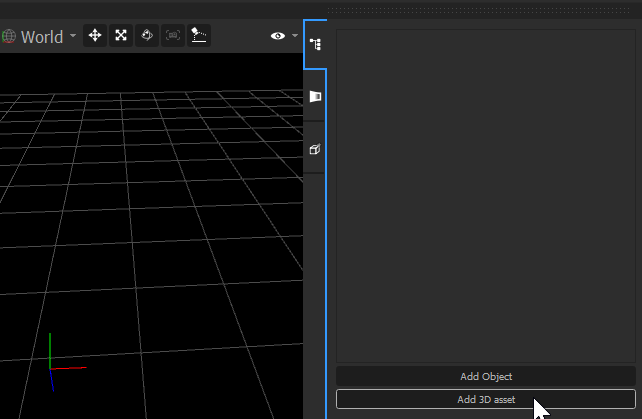
FBX import
Import the FBX in Onlyview, like any other media: Drag&drop it into the MediaList, or click Add Media.
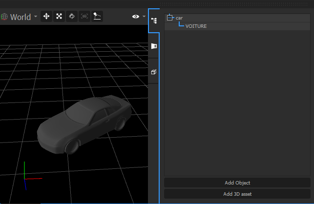
Onlyview scene creation
Create a 3D scene in Onlyview, which will contain the FBX and any other content. The easiest way is to drag&drop the FBX from the MediaList to the timeline.
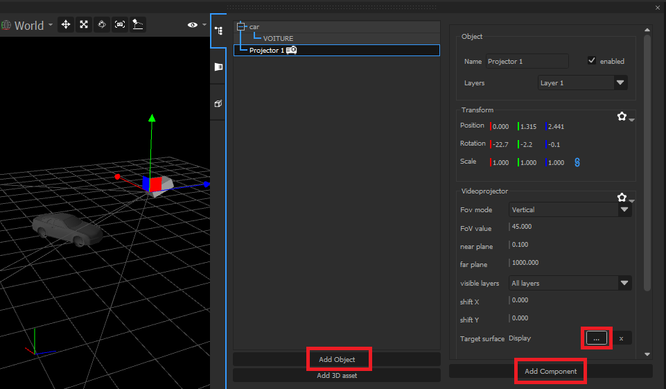
Creation of the Videoprojectors
You need Videoprojectors to “capture” the scene on the Media Servers. To create a Videoprojector, click “Add Object”, then “Add component”, and select “Videoprojector”. The object can be manipulated in the 3D preview; position it approximately where it is in reality.
You must then configure the projector to select which Media Server should render this view. In the inspector, click on the […] button of the Target Surface. You can then select the Media Server, or if you have a multi-output setup, which part. Alternatively, you can also output on a TextureArea, but you must then make sure that the TextureArea is visible on the desired Media Server by creating a cue.
If you have cameras in the FBX, they will also be imported as videoprojectors.
Creation of the material
The Media Servers are now rendering the scene, but since there is no light, it’s probably completely black, so you don’t see anything. You need to configure the material of the mesh so that it emits light.
Create a TextureArea, called for instance “3d texture” and put a media in it. Click on the 3D object, and in its inspector, click on the […] button of the Emissive field, and select your new TextureArea. This will have two effects:
In Producer’s 3D preview, the 3D mesh will be textured with the TextureArea’s content.
On Media Server, the 3D mesh will appear, also with the textured media.
Manual calibration
Since you positioned the Videoprojector approximately, the projected image will not perfectly match the real building or shape. You need to calibrate the Videoprojector’s position and lens so that Onlyview knows the real characteristics of your projector. Go in Manual Calibration mode, then click on a vertex of the scene. This will create a small cross on Producer, and a big black and white cross on the Media Server. Using the right click, start dragging the vertex to where it should really be in real world.
After a few points, the projector will snap into place, and the whole image should be projected correctly on the building.
Components
This section lists the various components that can be added to 3D objects. Each object can have multiple components, but only one of each kind; each component adds a behavior to the object.
Transform
Transforms give the position, orientation and scale of objects. It is the only component that is mandatory.
Mesh
A mesh contains a single geometry, and the material used to render the geometry. By itself, a mesh is not enough to have an image – you also need either a Camera, a Videoprojector, or an Unwraprenderer.
Materials can be given an emissive TextureArea, which will be visible when rendering, but the mesh needs to be UV-unwrapped. If your mesh doesn’t have any texture coordinates, you either need to unwrap it in a 3D package, or to create another object which projects a Decal on it.
Videoprojector
A Videoprojector is a virtual camera that renders the scene from a specific point of view. Unlike the Camera component below, Videoprojectors are taken into account when computing the illumination of the stage, when computing the softedge, or when using AutoCal.
Videoprojectors need to have their datasheet set, otherwise some features may not work.
They can render on different surfaces:
Media Servers (on the full Media Server output for Media Servers that have only 1 output; or on each sub-part of any Media Server, for Media Servers that have multiple outputs)
TextureAreas
Outputting directly on a Media Server is more straightforward, but outputting to an intermediate TextureArea can have several benefits: you can more easily adjust the output resolution, you can animate the deformation, etc.
Camera
A Camera renders the scene from a specific point of view, just like Videoprojectors; but unlike Videoprojectors, they don’t take part into any lighting computation (illumination mode, resolution mode, AutoCal, etc).
It is used to provide customer previews.
Unwraprenderer
Unwraprenderer renders the scene in a mesh’s UV coordinates.
Decal
Decals provide an easy-to-use alternative to manually unwrapping the 3D mesh in a separate 3D editor.
Decal components should not be created directly on the mesh, but on a separate object. A decal will behave like a virtual gobo light, that will project the contents of a TextureArea on whatever mesh is on its path
Multiple decals can be added in the same scene; however, they currently overlap in an unspecified order, to you should avoid overlapping multiple decals in spectator-visible zones.
TrackingCamera & TrackingZone
Together, these two components configure the Tracking Study mode. See the related section.
Light
Lights add either omni-directional lights (light bulb), or directional lights (sun). These lights can’t have any media playing on them – they can have only one color.
Lookat
This component permanently rotates an object towards another object.
PointCloud
Point clouds are like meshes, but without triangles: only the vertices are known. Point clouds are usually the output of a 3D scan, either from a LIDAR or from AutoCal. Onlyview accepts point clouds in OBJ format.
Preview modes
Onlyview offers several preview modes.
Media
This is the default mode. The 3D environment is rendered normally, just like on the Media Servers. The only difference is that on Producer, there is a small additional lighting, so that even a fully dark scene, without any projected media or light, can be seen and navigated.
Resolution
This mode shows the effective resolution of the projectors on the target surfaces. This includes the deformations of the pixels due to the projector being at an angle.
To avoid cluttering the view, each square represents a 10x10 px area.
Illumination
This mode helps analyzing and studying the amount of light that arrives on the stage. It is especially useful to study the number of needed projectors and designing the lighting rig.
You can set the target illumination that is requested by the customer in the top-right box, and the viewer will show the illumination of the stage, in lux, at each point of the mesh.
Red colors represent problematic areas where the lighting does not meet the requirements; blue colors represent the area that are lit more than enough, which is often the case on projectors overlap to allow for softedges; and yellow colors are lit just enough.
Tracking study
Tracking consists in making a 3D object follow a performer or a stage element. This can be done using a variety of techniques, including OptiTrack, BlackTrax, LPM, etc. See the Devices and ActionGraph sections for more information.
Using optical tracking, it is often challenging to foresee the position of the tracking cameras, because many criterion should be taken into account: the desired precision, the relative position and orientation of the cameras, their number… Onlyview’s Tracking study tool helps designing the cameras rig with precise and objective data, instead of guesswork.
To use this mode, first create a new object, and add it a Tracking Zone component. This area will be analyzed by the algorithm. Note that height is taken into account too, which is important because tracking people or large objects don’t only require visibility on the ground, but also above.
Then create another object, and add it a Tracking Camera component. Fill in the resolution and field of view, and position the camera where you want. Do the same so that you have at least 3 Tracking cameras looking at the Tracking Zone from different angles.
The Tracking Zone will then show color-coded cubes which will highlight problematic areas where tracking quality does not match the requirements. The color code is the same as for the Illumination mode.
Full reference
Keyboard shortcuts
- Select a 3D object: Left click
- Toggle 3D object selection: Ctrl + Left click
- Pan view: Middle click & drag
- Rotate view: Right click & drag
- Rotate around pivot: Alt + Middle click
- Zoom: Wheel
Move object
- Free move: Left click & drag
- Move 1 unit: Ctrl + Left click & drag
- Move 0.1 unit: Shift + Left click & drag
Scale object
- Free scale: Left click & drag
- Scale 1 unit: Ctrl + Left click & drag
- Scale 0.1 unit: Shift + Left click & drag
Rotate object
- Free rotate: Left click & drag
- Rotate 5 degrees: Ctrl + Left click & drag
- Rotate 1 degree: Shift + Left click & drag
- Select previous object in tree: Up
- Select next object in tree: Down
- Rename object in tree: F2
- Remove object in tree: Delete
- Contextual menu: Right click
- Copy object: Ctrl + C
- Paste object: Ctrl + V
- Paste object position (scale, rotation): Ctrl + F2 (F3, F4)
- Focus on selected 3D objects: F
View-through mode
- Zoom: Wheel
Calibration mode
- Add point / Select point: Left click
- Move point: Left click & drag
- Move to desired position (target surface mandatory): Right click & drag
- Move 1 px: Left/Right/Up/Down
- Move 0.2 px: Shift + Left/Right/Up/Down
- Move 10 px: Ctrl + Left/Right/Up/Down
Alignment mode
- Select point: Left click
- Move point: Left click & drag
- Move to desired position: Right click & drag
- Remove point: Left click on a point
- Pan view: Middle click & drag
- Zoom: Wheel