Autocal
When working in the 3D workflow, OnlyView can automatically calibrate the position, rotation, and lens of the projectors. For this, additional hardware is required: specific cameras that will analyze the scene.
What AutoCal does:
It guesses the position of the 3D cameras and projectors
It provides a 3D scan of the scene, as a point cloud
It re-aligns the cameras, the projectors and the point cloud so that it matches the real scene
The end-result is that each Display automatically outputs the correctly-deformed image. No manual deformation (for instance, with WarpNet) is required, expect for optional fine-tuning.
What AutoCal doesn’t do:
It does not provide a 3D mesh. You can take the output point cloud and model the scene based on it, but it is a manual process.
It is not a tracking system. Auto-calibration takes some time, with very visible light patterns being projected, so it is not something you can do during the show.
Hardware installation
Cameras
OnlyView uses Lucid Vision, OptiTrack or Allied Vision ethernet cameras.
You will need several cameras, arranged so that each part of the scene is seen by a minimum of two cameras; ideally all with the same resolution. Usually, putting the cameras at the same position than the projector is a good first-guess, but keep in mind that the cameras must be sufficiently spaced so that the depth perception can be precise enough.
The cameras are PoE, so you will need a PoE switch with a sufficient total power budget (5W per camera).
The cameras are Gigabit-ethernet. When connecting multiple cameras on a single switch, you must use a 10-Gigabit switch, and Producer must have a 10Gb connection to this switch:
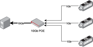
The cameras expect a DHCP in the network, so that they can get their IP addresses. If you are using manual addresses, you need to configure each camera using Arena Config.
Follow the Arena SDK documentation for Windows in ArenaView to correctly setup the Windows environment.
In ArenaView, you can open a camera, and start streaming its content to check that it’s correctly positioned.
Aim for the object or the desired zone, precisely set the focus, adjust the diaphragm and the exposure time (see the “Step 7 – Find matches” section for more info).
Markers
Markers are an optional feature that can help automating the process. For a fully manual approach, see the “Manual Alignment” section.
There are two methods available to use markers, each with pros and cons.
ArUco markers
One way to make the 3D scan and the reality match is to use small markers. You can print them from http://chev.me/arucogen/ (using the 4x4 dictionary). Print at least markers 0 to 3. The physical size depends on the scale of your project, but the markers must take around 80 pixels of the camera’s image, so for a stadium, you may need 2m*2m markers.
This method has the advantage of being more robust to small changes in the environment and the detection precision may be higher than the other method. The obvious drawback is that these markers are visible from the public and the locations where you can place them is limited.
These markers will need to be positioned at known, measured locations (for instance using a laser rangefinder on large flat surface, or on recognizable locations, like buildings corners)
For better performance, here are a few extra guidelines with the markers:
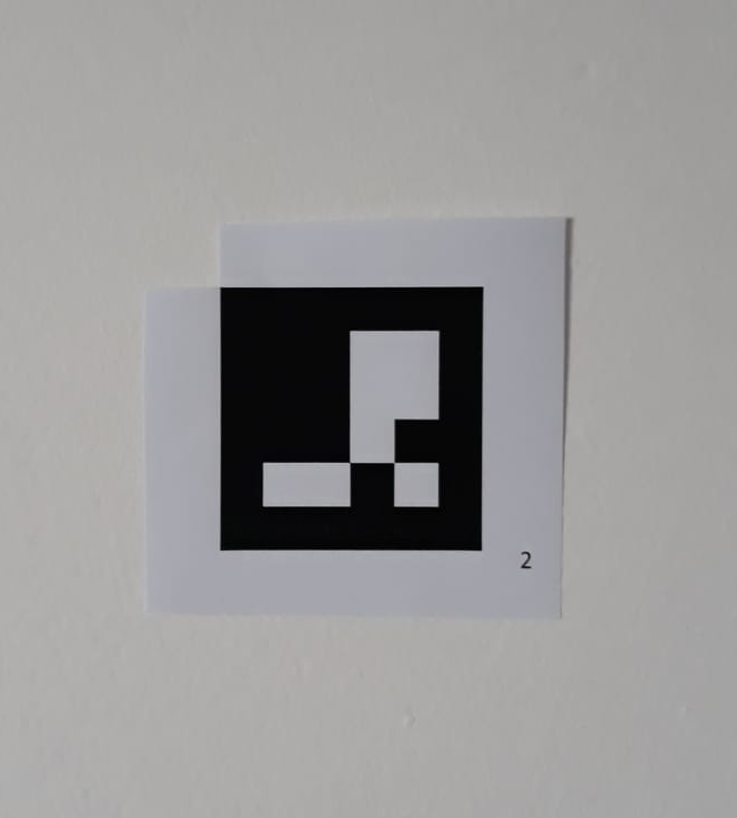
They must be printed with a white border, approximately the size of the squares
It is recommended to print the marker ID nearby, so that it’s easier to read
The recognized point is the top-left corner
Since there is an additional white border, you can punch a hole in the top-left corner to position it accurately
An example marker, with its corresponding ID (for easier handling), and the top-left corner made accessible.
Template matching
This method doesn’t use any physical marker, and instead uses recognizable areas of the stage, such as the corners of the screen, as anchor points.
It requires you to configure the markers manually the first time. Once this step is done and the markers recalibration settings set, OnlyView will be able to look for new locations of the markers.
Template matching has several limitations which restrict locations where they can be used:
They are more sensitive to lighting conditions
They are sensitive to repeating or linear patterns
It presents however some advantages compared to ArUco markers:
Almost any existing feature of the stage can be used.
Since these features are part of the stage, no physical marker is visible by the public.
Procedure
Step 1 – Create the 3D scene
Create the 3D scene in OnlyView as usual:
Import your FBX
Add it in the timeline
Add some media by either setting the material’s emissive texture, or by creating a decal
Add and configure the Videoprojectors. The output TextureArea/Screen must be set.
If you output to TextureAreas, they must be actually visible on the stage.
Position approximately the Videoprojectors.
Do an Online to make sure that the Displays correctly display the media.
At this point, your show is mostly ready – the only missing piece is that the projectors are not aligned.
Step 2 – ArUco markers (optional)
Position the printed markers at interesting points of the scene.
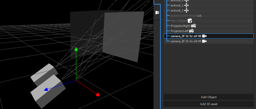
Next, in the 3D, create Calibration Points, and place them at the exact same location. Name them autocal_0, autocal_1, etc, where “0” and “1” corresponds to the IDs of the real markers.
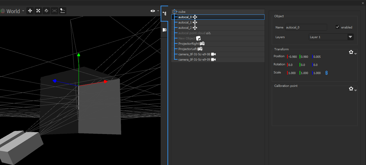
The autocal points in the 3D (and their Calibration Point component). Point 0 is in the corner.
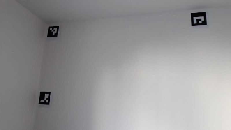 The printed markers.
Point 0 is also in the corner.
The printed markers.
Point 0 is also in the corner.
Step 3 – Add the cameras
- Open the AutoCal window :
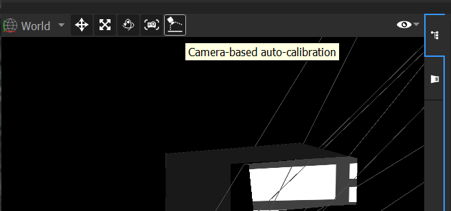
- Click “List Cameras”. The ethernet camera will be automatically discovered, and added in the scene. Each camera is named after its MAC address, which is visible on the camera itself:
- Close the AutoCal window
- The cameras were added in the scene. Position them approximately: rough position and orientation. Pay special attention to not invert cameras: the camera on the right really must be on the right ! Check the names to be sure.
- Re-open the AutoCal window
The rest of the steps is mostly to click the buttons one after the other, but each one will be detailed, which will be helpful for troubleshooting.
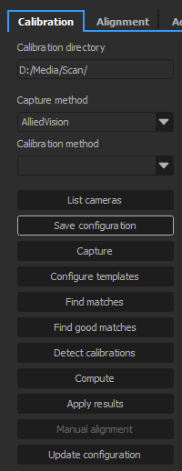
Step 4 – Save the configuration
This button creates a file called setup.json in the choosen directory (by default, D:/Scan)
Click it, and check that this file is correctly created.
Step 5 – Capture
This procedure will display custom patterns on each projector, and take pictures of each pattern.
It is important that the camera’s exposure is correctly set beforehand. Open the lens’ iris as much as you can while still keeping a sharp image, then open Lucid Arena, and find an exposure that gives a good exposition; then use this value in the Advanced tab, on the Exposition setting. To troubleshoot exposure issues, see the next section.
Step 6 – Configure templates (optional)
This step is required if you want to use template matching. The button will take you to the “Alignment” tab. In this tab, you will have to configure the match points.
The tab contains all the cameras available, with the 3D mesh of the scene overlayed as a wireframe. Like manual alignment, the goal is to align the blue lines with the scene camera backdrop.
Be sure to choose recognizable points in the image following the rules mentioned in the presentation of template matching.
To place a match point, simply click on a calibration point and drag the mesh point to the location where it should be. When a match point is selected, you will have to check “Auto-Recalibration” and eventually configure the size of both template and search area.
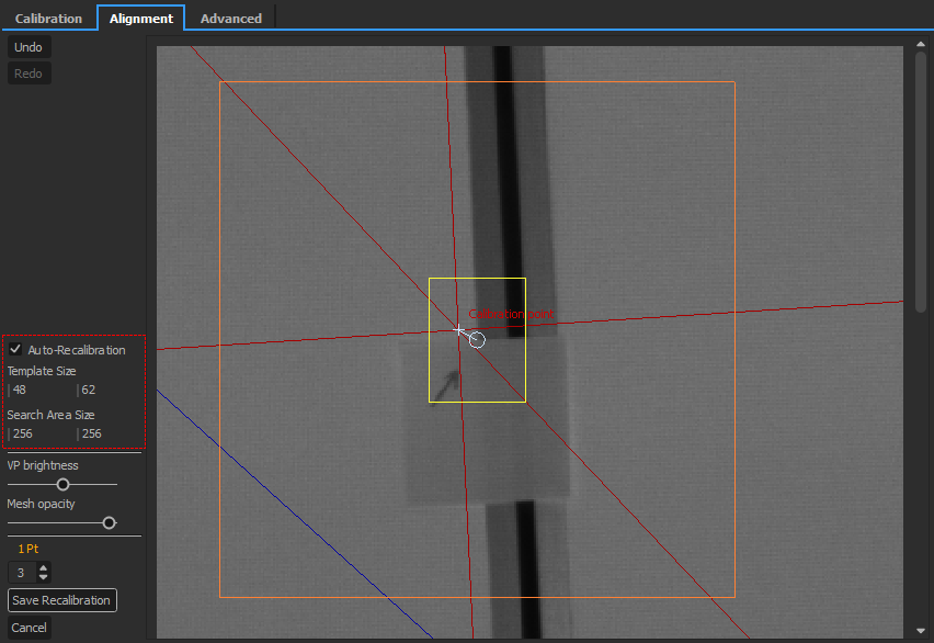
Be mindful of too big areas since template matching is sensible to changes in the image other than translation of the view. Likewise, the template should be large enough to have some features of the image that are recognizable.
Repeat the process for several points on each camera.
Once you have finished, click on “Save Recalibration”. This button will save the points that are to be recalibrated and create a copy of each camera_XX/white.png image of each camera to use as the reference when performing the point detection later. If you don’t save, leaving the tab will discard any modifications.
Note that if you redo this step after a first calibration detection, the view will also display where the match point was last seen.
Step 7 – Find matches
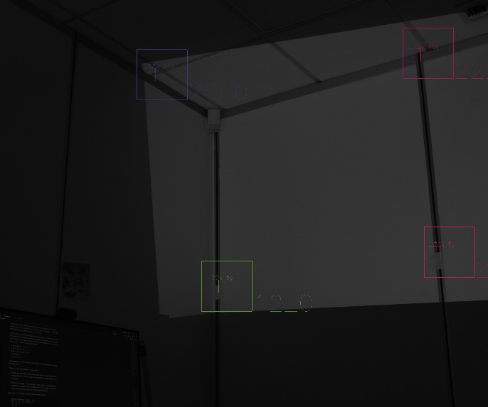
This step analyses the pictures of the capture step. The folders proj_XX/camera_XX/ will contain a new image, out.bmp, which represents the points where a camera has successfuly analysed the projector’s patterns. It should look like this:
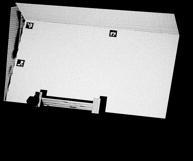
If out.bmp is mostly black, you need to make sure that the camera’s exposure was sufficient.
Open one of the images above:
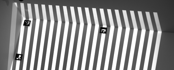
The important criterion is the difference of luminosity between the black and the white stripes.
If the white stripes are overexposed/burnt: reduce the exposure
If the white stripes are too dark: increase the exposure
If the black stripes are too bright: the ambient lighting is to high
The difference of luminosity between the white and the dark stripes must be more than 5/255 (if needed, open the image in Photoshop and compare the colors with the picking tool).
Click on “Find good matches”. It will usually find between 500 and 2000 points, depending on your scene. If less, check the “out.bmp” pictures as explained above. If more, increase the “subsampling” parameter in the Advanced tab.
Step 8 – Detect calibrations (optional)
Do this step if you choose to do either ArUco or template matching recalibration.
ArUco
The pictures in white/camera_XX/ will be analyzed to search for the printed markers. If not enough markers are found, look at white/camera_XX/white_markers.bmp
If a marker is not found: it may be too small, or lit in an unusual way. Move markers a few centimeters away from concave corners (and the related Calibration Points), because light from the other wall may interfere.
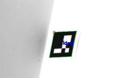
Marker 2 found, in the top-left corner of the marker. Notice that the corner is darker, which interferes with the detection.
Template matching
The pictures in white.png and calibration_reference.png in white/camera_XX/ will be analyzed to find the new locations of match points.
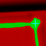
For debugging purposes, analysis of a match point produces an image where the matching score of the template at a specific pixel in the search area is represented by the pixel light level. If the score is above the allowed threshold, it will appear green. Otherwise, it will appear red. A blue marker is placed on the pixel that has the best score.
Possible output:
In addition to individual match point debug images, two copies of the captured pictures will be produced with markers info burned into them. There is one for what was expected based on the calibration reference and another for what was actually found with the new capture.
Possible output:

Finding a marker can fail for many reasons, for example, if there is something hiding partially or completely the point of interest. This is also the case if the point of interest goes outside of the search area. A frontier between light and dark area that has moved may offset the marker.
OnlyView do its best to discard matches that he knows invalid but unfortunately this process is not 100% reliable, so invalid matches may still be considered during the computation step, causing wrong results.
Step 8 – Computation
Click on “Compute”. This will take a few minutes. Ideally, the average error should converge to a small value (1.0 or below), and you should not have too many outliers (50 outliers for 1000 points is acceptable).
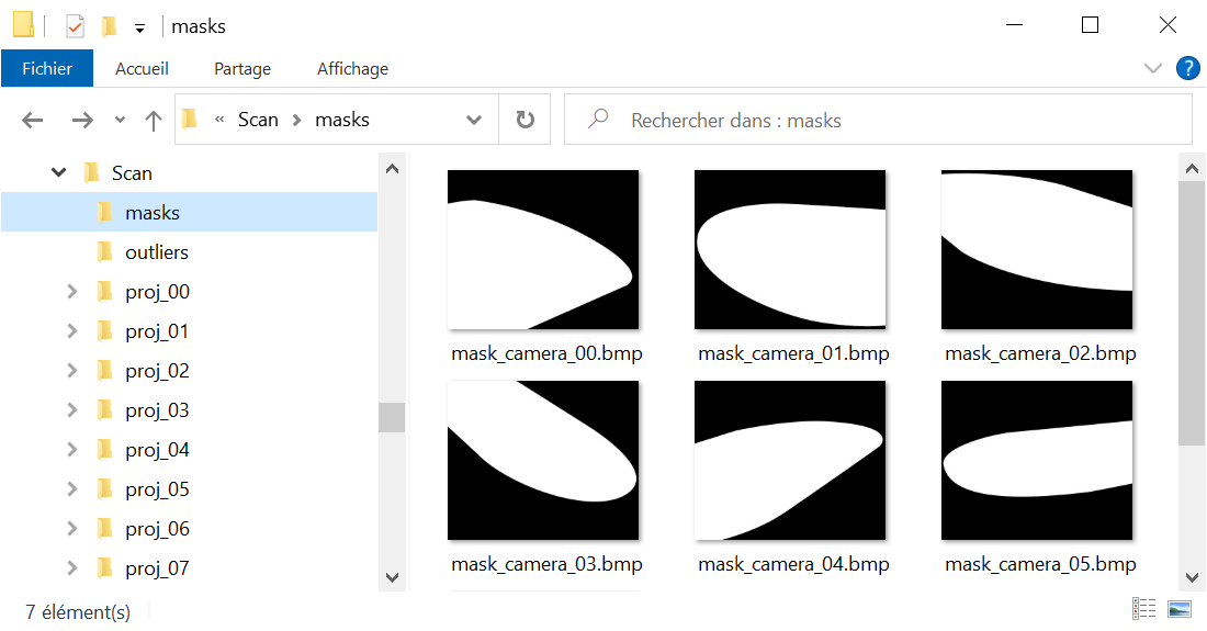
Once finished, if you have too many outliers: check the “out.bmp” pictures. If you notice that many points are found on reflexive surfaces (metallic railings for instance), this may be a problem. You can manually create masks to fix the issue: Copy the images in the “white/” folder, and manually trace them in Photoshop so that forbidden zones are black, and valid zones are white. The masks must have the same resolution as the original pictures.
It is not necessary to have one mask by camera: you may only make masks for the problematic ones.
Then, restart from the “Find matches” step.
Click “Apply results”. The videoprojectors and cameras will be correctly positioned, and a new object called “autocal point cloud” will be created. It can be found in out.obj for further editing in a 3D software.
Step 9 – Manual alignment (optional)
Unless you used markers, the projectors and cameras will be correctly positioned with respect to the point cloud; but Onlyview now needs to match this 3D scan on its 3D scene.
To do this, go on the “Alignment” tab. Like template configuration, all cameras will be visible, with the 3D mesh overlayed. The goal of this step is to align the blue mesh on the camera images.
Choose a recognizable part of the image, for instance a building corner, and click on the related 3D vertex of the mesh. Then, using the left mouse button, drag&drop this vertex on the correct image position.
Do this for multiple points, and from various cameras. After a few points, the 3D scan should snap into place. After some finetuning, the auto-calibration process is finished.
Step 10 – Update the configuration
If you are satisfied with the result, you can click on “update configuration” so the calibration configuration will now use already well calibrated data.
Improving the quality
Once you roughly calibrated the system with approx 1000 points, you can finetune the result with a bigger point cloud.
In the Advanced tab, reduce the “bucket size” parameter to 32 or 16, and subsampling as low as possible, ideally 1 (but “Find Good Matches” will take longer). Then re-start the process (but skip the Capture part, since nothing moved in real life). The goal is that the “Find Good Matches” step gives you approximately 10’000 points. When you finish the process, compare the output point cloud and the mesh you’re using. Don’t hesitate to scale them to better view the difference. At this point, you may need to re-mesh so that the 3D model correctly matches the reality.
In this example, the scanned object was a perfectly flat ground. But when exaggerated 40 times, the relief becomes obvious. The 3D mesh used for projection needs to take these variations into account.
Automation of the process
It is possible to automate the auto-calibration process.
As a prerequisite, the auto-calibration must have been done once using the markers system. These markers can then be removed for the next runs.
As the system now has points of reference, you can create a standalone auto-calibration action through a Quick Key or a Command Cue from the Producer Object.
Select the “Autocalibrate 3D scene” action and choose the available scene to calibrate. Note that the scene must be used as a Cue in the show to be available in the list. Finally, press “OK”.
Now, when executing the Quick Key, or when the locator triggers the Command Cue, an auto-calibration process will operate. It will automatically capture the images, find the matches, the good matches, compute a solution and apply it if the results are considered good enough.