ArUco and manual alignment
If template matching is not suitable for your setup, two alternatives are available. ArUco markers offer more robust detection at the cost of physical setup; manual alignment requires no setup but is time-consuming and depends on user precision.
ArUco markers
This method uses small printed squares placed at known, measured locations on the stage. Compared to template matching:
- More robust to small changes in the environment
- Detection precision may be higher
- Drawback: markers are visible to the public and must be placed at measurable, known positions
ArUco markers setup
Info
Do this before starting the main procedure. The markers must be physically in place before the Capture step photographs them.
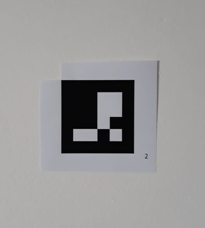
You can print the markers from arucogen (using the 4x4 dictionary). Print at least markers 0 to 3. The physical size depends on the scale of your project, but the markers must take around 80 pixels of the camera's image, so for a stadium, you may need 2m×2m markers.
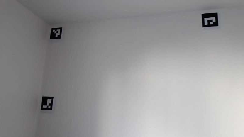
These markers will need to be positioned at known, measured locations (for instance using a laser rangefinder on large flat surface, or on recognizable locations, like buildings corners)
For better performance, here are a few extra guidelines with the markers:
-
They must be printed with a white border, approximately the size of the squares
-
It is recommended to print the marker ID nearby, so that it's easier to read
-
The recognized point is the top-left corner
-
Since there is an additional white border, you can punch a hole in the top-left corner to position it accurately
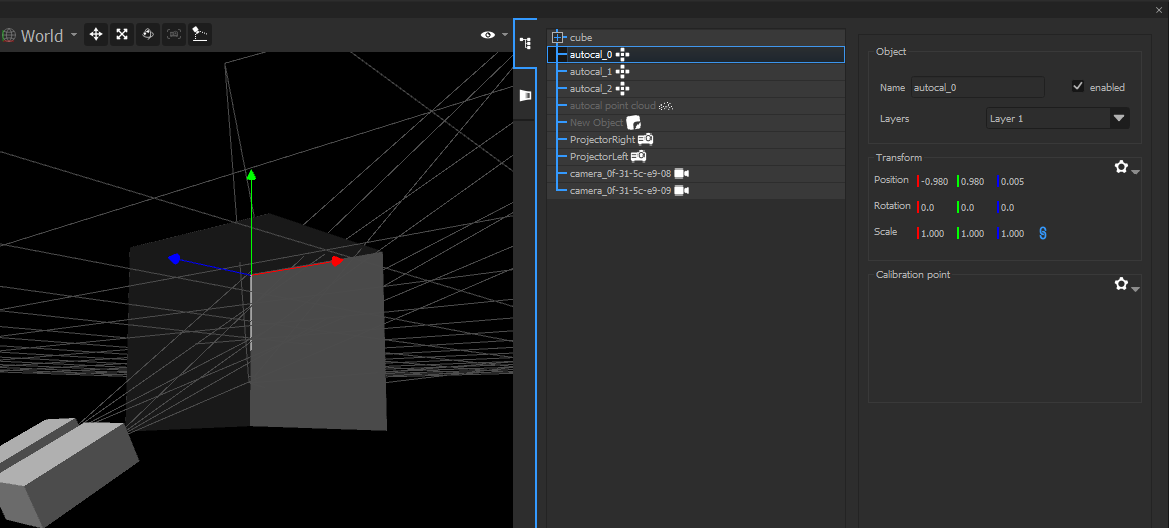
Position the printed markers at interesting points of the scene.
Next, in the 3D, create Calibration Points, and place them at the exact
same location. Name them autocal_0, autocal_1, etc, where "0" and "1"
correspond to the IDs of the real markers.
Detect calibrations
Info
Do this after Calibration Step 2 (Find matches) and before Step 4 (Computation). The detected marker positions are used by the Computation step to anchor the result to the real world.
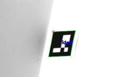
The pictures in white/camera_XX/ will be analyzed to search for the
printed markers. If not enough markers are found, look at
white/camera_XX/white_markers.bmp
If a marker is not found: it may be too small, or lit in an unusual way. Move markers a few centimeters away from concave corners (and the related Calibration Points), because light from the other wall may interfere.
Manual alignment
This method requires no physical setup. The user manually drags mesh vertices onto matching points in the camera images, directly telling OnlyView how the 3D scene maps to the real world.
It is the most flexible method but also the most time-consuming, and the accuracy depends on the user's precision.
Info
Do this after Calibration Step 4 (Computation). The point cloud must exist before it can be aligned to the 3D scene.
At this point, the projectors and cameras are positioned within the point cloud, but the point cloud itself still needs to be aligned to Onlyview's 3D scene.
To do this, go on the Alignment tab. All cameras will be visible, with the 3D mesh overlayed. The goal of this step is to align the blue mesh on the camera images.
Choose a recognizable part of the image, for instance a building corner, and click on the related 3D vertex of the mesh. Then, using the left mouse button, drag&drop this vertex on the correct image position.
Do this for multiple points, and from various cameras. After a few points, the 3D scan should snap into place. After some finetuning, return to Step 6 (Update the configuration).