Procedure
This is the standard calibration procedure, using template matching as the alignment method: recognizable features of the stage — such as screen corners — serve as anchors. No physical setup is required; after a one-time configuration, OnlyView re-detects these points automatically on each subsequent calibration.
For alternative alignment methods, see ArUco and manual alignment.
First-time Setup
Step 1 -- Create the 3D scene
Create the 3D scene in OnlyView as usual:
-
Import your FBX
-
Add it in the timeline
-
Add some media by either setting the material's emissive texture, or by creating a decal
-
Add and configure the Videoprojectors. The output TextureArea/Server Output must be set.
-
If you output to TextureAreas, they must be actually visible on the stage.
-
Position approximately the Videoprojectors.
-
Do an Online to make sure that the Media Servers correctly display the media.
At this point, your show is mostly ready -- the only missing piece is that the projectors are not aligned.
Step 2 -- Add the cameras
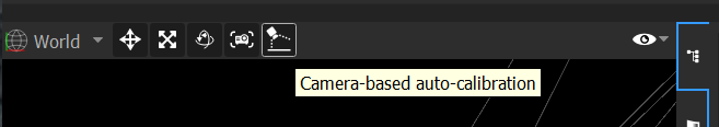
- Open the AutoCal window :
-
Make sure cameras are disabled in Arena SDK first.
-
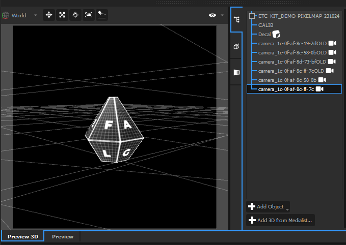
Click List Cameras. The ethernet cameras will be automatically discovered, and added in the scene. Each camera is named after its MAC address, which is visible on the camera itself:
-
Close the AutoCal window
-
The cameras were added in the scene. Position them approximately: rough position and orientation. Pay special attention to not invert cameras: the camera on the right really must be on the right ! Check the names to be sure.
- Re-open the AutoCal window
The remaining steps are mostly sequential button clicks — each is detailed below to help with troubleshooting.
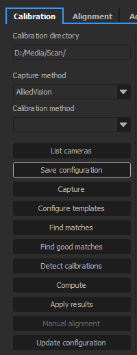
Step 3 -- Save the configuration
This button creates a file called setup.json in the chosen directory.
Recommended path: D:/Media/Scan/<projectname>/
setup.json stores the videoprojector positions — if hardware moves, save again before recalibrating.
Click it, and check that this file is correctly created.
Step 4 -- Capture
This procedure will display custom patterns on each projector, and take pictures of each pattern.
It is important that the camera's exposure is correctly set beforehand. Open the lens' iris as much as you can while still keeping a sharp image, then open Lucid Arena, and find an exposure that gives a good exposition; then use this value in the Advanced tab, on the Exposition setting. To troubleshoot exposure issues, see Calibration, Step 2 (Find matches).
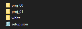
After the capture, the scan directory will contain proj_00/, proj_01/, white/ and setup.json:
Step 5 -- Configure templates
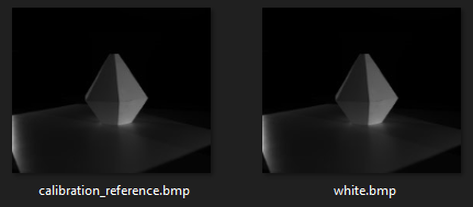
This step configures the template matching match points. The button will take you to the Alignment tab. It needs the captured white images as a reference to detect template positions on future runs — only needed on the first run.
The tab contains all the cameras available, with the 3D mesh of the scene overlayed as a wireframe. The goal is to align the blue lines with the scene camera backdrop.
Be sure to choose recognizable points. Template matching has two limitations to keep in mind:
- Sensitive to changes in lighting conditions
- Does not work well on repeating or linear patterns
To place a match point, simply click on a point (mesh vertex or calibration point) and drag it to the location where it should be. When a match point is selected, you can optionally configure the size of both template and search area.
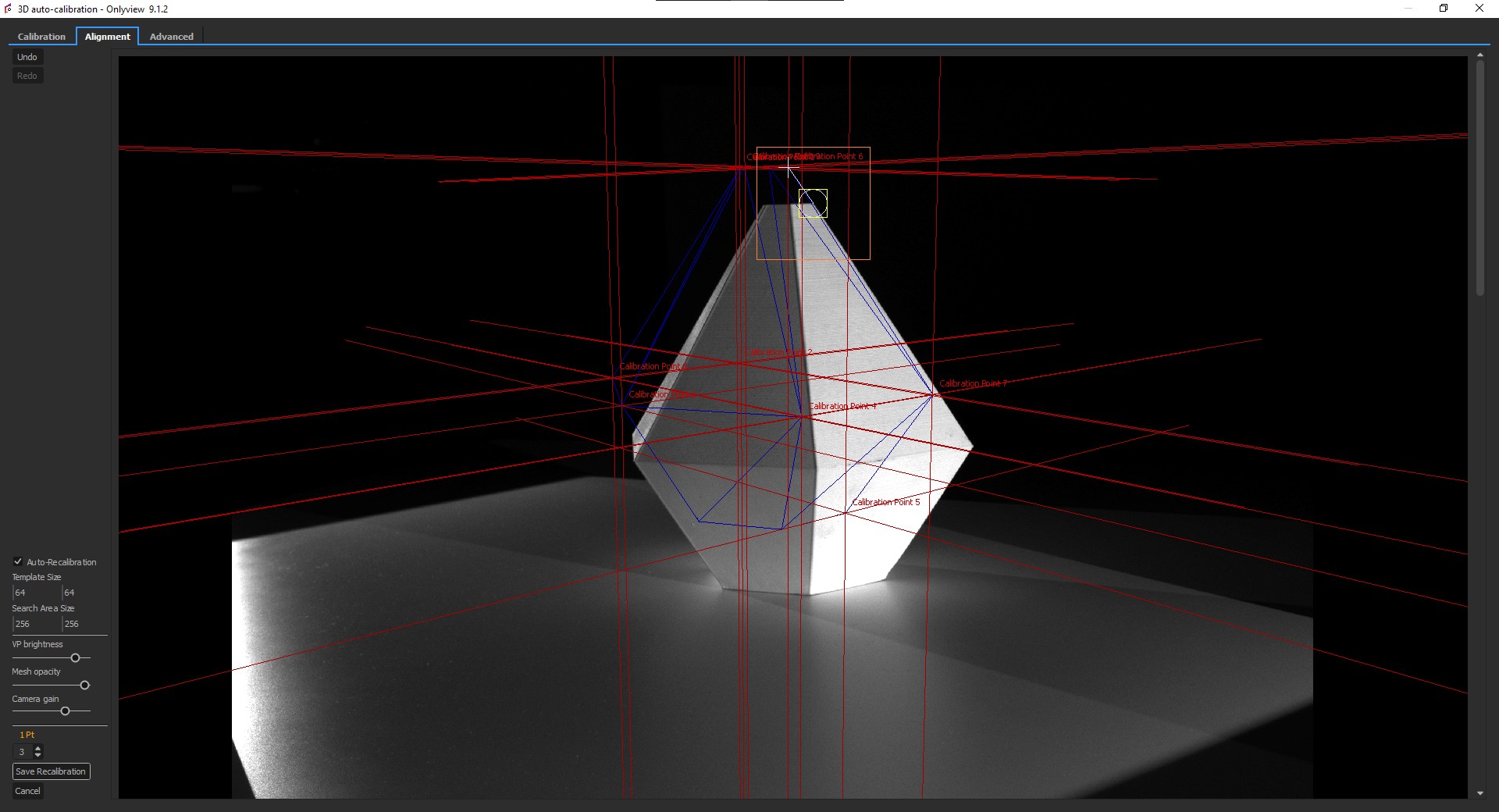
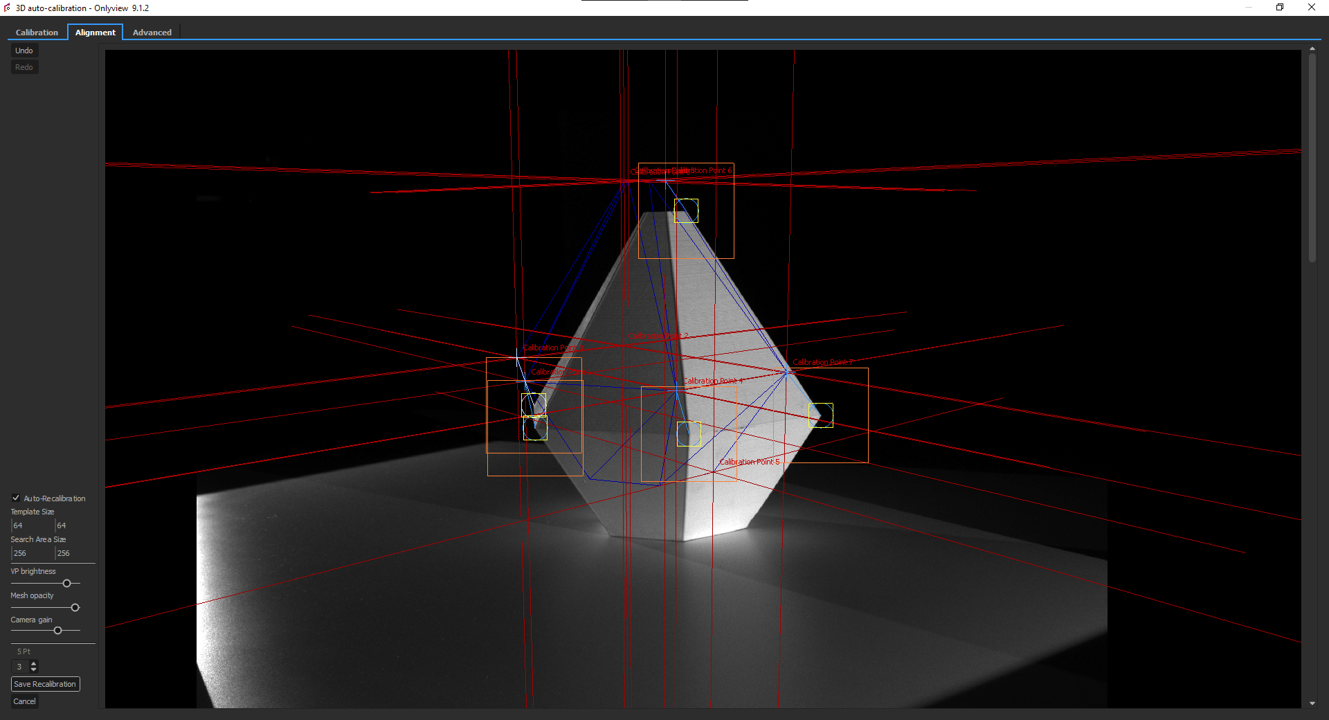
Be mindful of too big areas since template matching is sensible to changes in the image other than translation of the view. Likewise, the template should be large enough to have some features of the image that are recognizable.
Repeat the process for several points on each camera.
Once you have finished, click Save Recalibration. This
button will save the points that are to be recalibrated and create a
copy of each camera_XX/white.png image of each camera to use as the
reference when performing the point detection later. If you don't save,
leaving the tab will discard any modifications.
Note that if you redo this step after a first calibration detection, the view will also display where the match point was last seen.
Calibration
Step 1 -- Capture
Info
Skip this step if you just completed First-time Setup and no hardware has moved since.
Capture fresh images as described in First-time Setup, Step 4.
Step 2 -- Find matches
This step analyses the pictures of the capture step. The folders
proj_XX/camera_XX/ will contain result data and validation images.
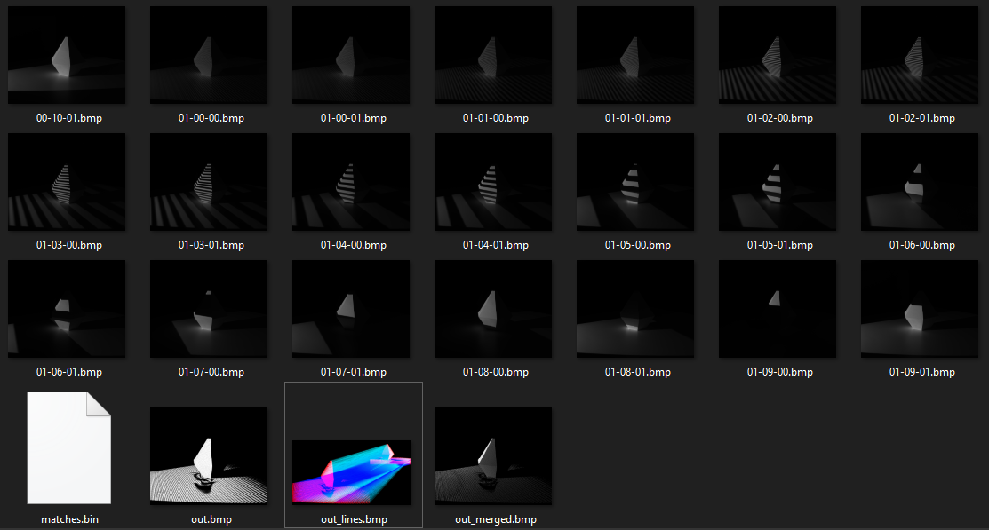
The image named out.bmp represents the points where a camera has successfully analysed the projector's
patterns. It should look like this:
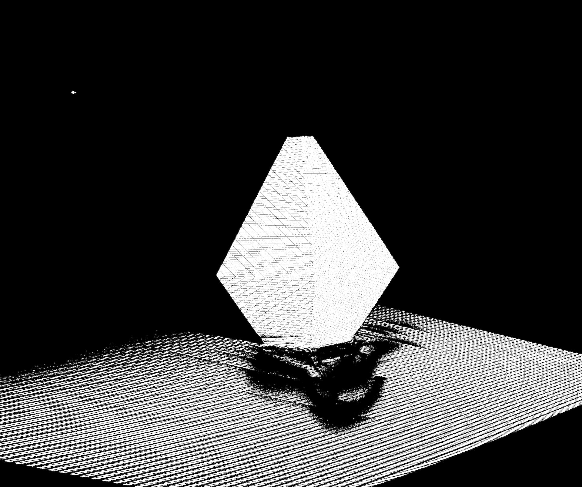
- ✅
out.bmpshows a dense point pattern → OK - ❌
out.bmpmostly black → camera exposure insufficient, recapture
Open one of the images above:
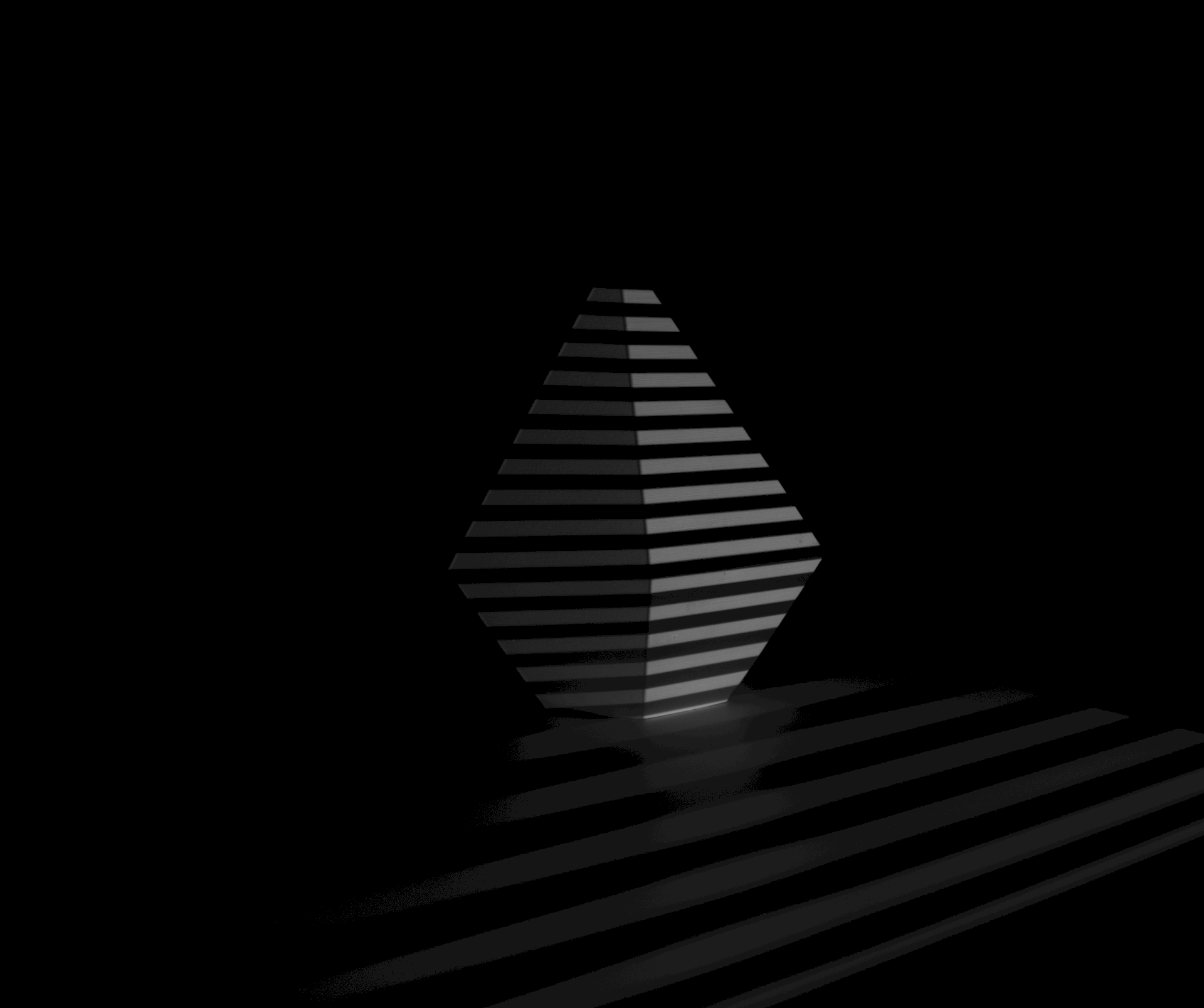
The important criterion is the contrast between black and white stripes:
- ✅ Clear contrast between white and dark stripes (> 5/255) → OK
- ❌ White stripes overexposed/burnt → reduce exposure
- ❌ White stripes too dark → increase exposure
- ❌ Black stripes too bright → reduce ambient lighting
Click Find good matches.
- ✅ 500–2000 points found → OK
- ❌ Fewer points → check
out.bmp(exposure issue) - ❌ More than 2000 → increase
subsamplingin Advanced tab
Step 3 -- Detect calibrations
For ArUco markers, this step detects the printed markers instead of template match points. See ArUco and manual alignment.
Click Detect calibrations. The white/camera_XX/ images will be analyzed to find the new locations of match points.
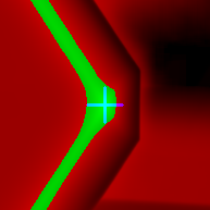
For each match point, a debug score image is produced: pixel brightness represents the matching score; above-threshold pixels appear green, below-threshold red, and the best match is marked in blue.
Two annotated copies of the capture are also produced — expected positions and actual positions — for visual comparison.

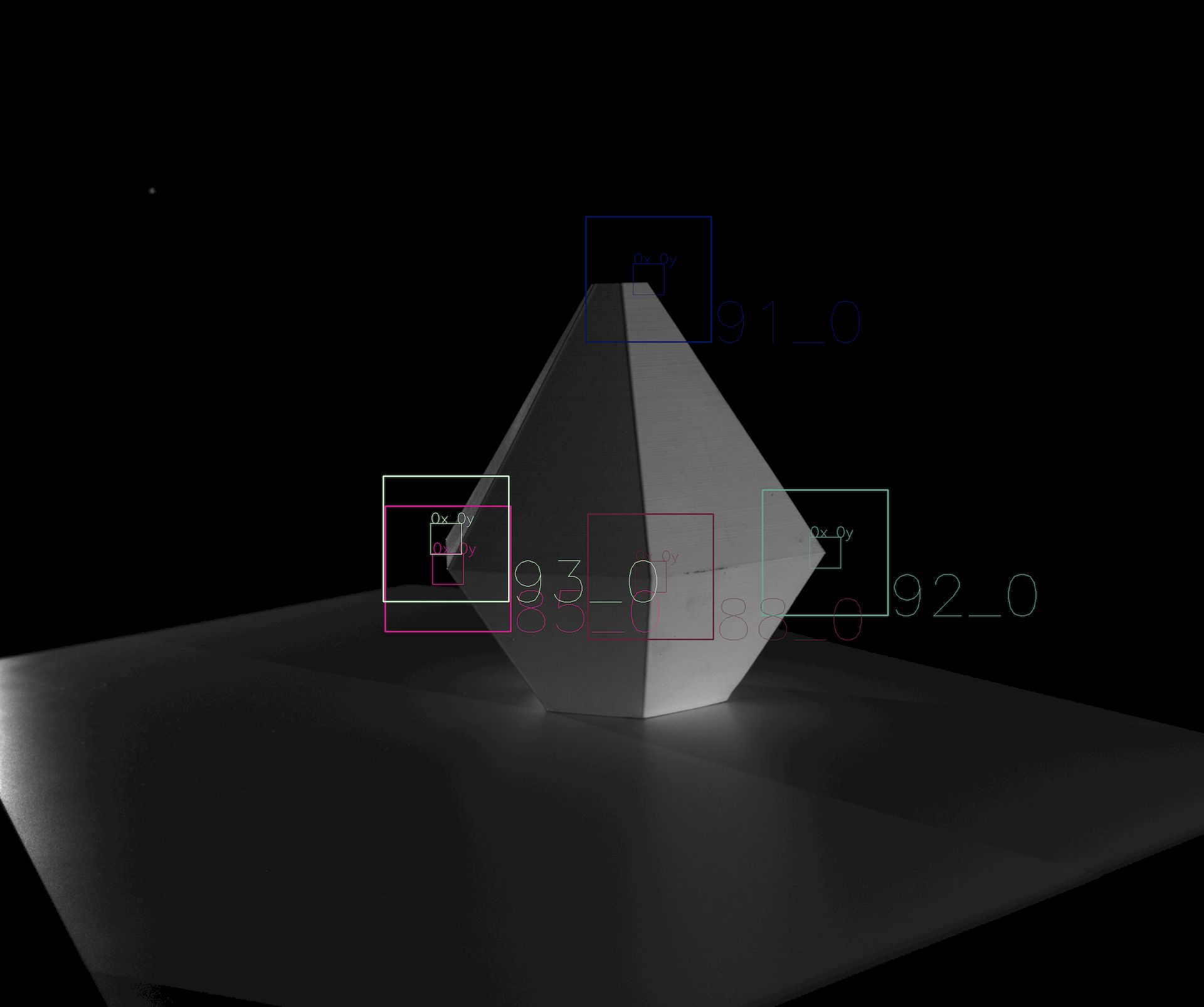
- ✅ Match points found near expected positions → OK
- ❌ Match points missing or offset → check the debug images above
Match point detection can fail or be offset for several reasons: an object partially or completely blocking the point, the point moving outside the search area, or a light/dark boundary shifting since the reference was captured.
Note: OnlyView discards known-invalid matches, but this is not 100% reliable — invalid matches may reach the computation step and cause wrong results.
Step 4 -- Computation
Click Compute. This will take a few minutes.
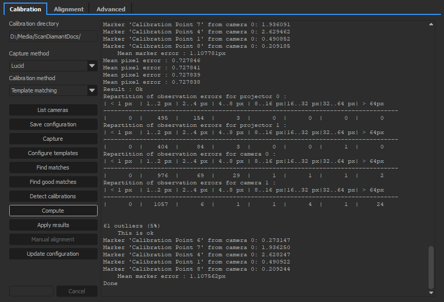
- ✅ Average error ≤ 1.0 → OK
- ✅ Few outliers (e.g. ~50 for 1000 points) → OK
- ❌ Too many outliers → check
out.bmp; if reflective surfaces are visible (e.g. metallic railings), see Creating masks below
Creating masks
Copy the images from the white/ folder and paint forbidden zones black in Photoshop (valid zones white, same resolution).
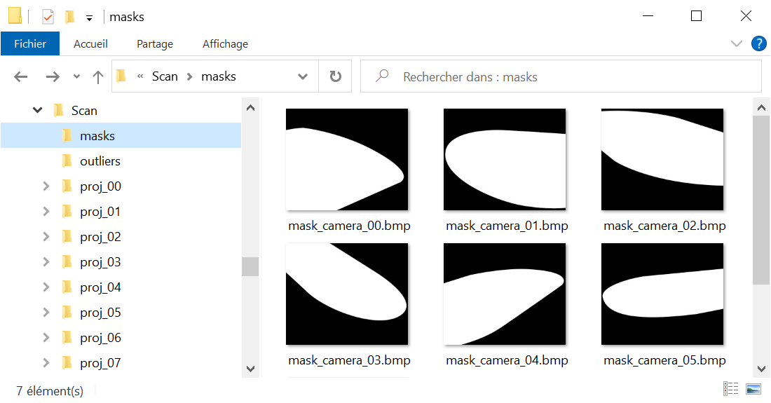
It is not necessary to have one mask per camera: you may only make masks for the problematic ones.
Then, restart from Step 2 (Find matches).
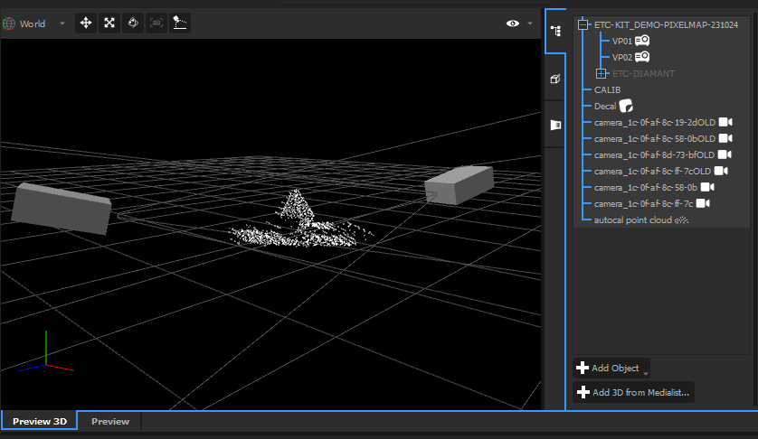
Step 5 -- Apply results
Click Apply results. The videoprojectors and cameras will be correctly
positioned, and a new object called "autocal point cloud" will be
created. It can be found in out.obj for further editing in a 3D
software.
Step 6 -- Update the configuration
If the result looks good, click Update configuration to save the calibrated positions as the new baseline for future runs.
Improving the quality
Once you have a rough calibration (~1000 points), you can finetune it with a larger point cloud.
In the Advanced tab:
- Set
bucket sizeto 32 or 16 - Set
subsamplingas low as possible, ideally 1 (note: Find Good Matches will take longer)
Re-run the Calibration procedure from Step 2 (Find matches). The goal is to yield ~10,000 points.
Once done, compare the output point cloud with your mesh — scale both to make differences visible. If they diverge, you may need to re-mesh so that the 3D model matches reality.
In this example, the scanned object was a perfectly flat ground. But when exaggerated 40 times, the relief becomes obvious. The 3D mesh used for projection needs to take these variations into account.
Automation of the process
It is possible to automate the auto-calibration process.
As a prerequisite, the auto-calibration must have been done once using template matching, so that OnlyView has reference points for future runs.
As the system now has points of reference, you can create a standalone auto-calibration action through a Quick Key or a Command Cue from the Producer Object.
Select the Autocalibrate 3D scene action and choose the available scene to calibrate. Note that the scene must be used as a Cue in the show to be available in the list. Finally, press OK.
Now, when executing the Quick Key, or when the locator triggers the Command Cue, an auto-calibration process will operate. It will automatically capture the images, find the matches, the good matches, compute a solution and apply it if the results are considered good enough.